When you click on links to various merchants on this site and make a purchase, this can result in this site earning a commission. Affiliate programs and affiliations include, but are not limited to, the eBay Partner Network.
proper installation of the cotter pins for the upper and lower ball joint castle nuts
I've posted this same post on the NCRS forum but without any replies, so I'm hoping there is at least one NCRS member over here on the CF who knows the answer(s) to my question(s). Thanks in advance.
Finally, we are in the process of reassembly of my 67�s front suspension and this greenhorn has a few questions about the proper installation of the cotter pins for the upper and lower ball joint castle nuts, and instead of presuming that I�m reading my manuals correctly (and then possibly doing things incorrectly) I�m reaching out to those with knowledge to prevent me from making mistakes and having to redo things.
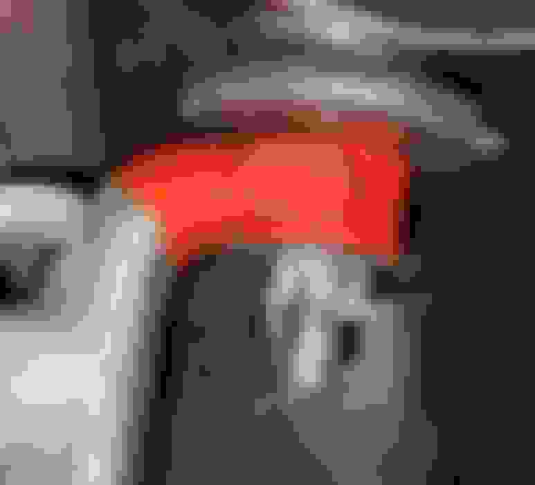
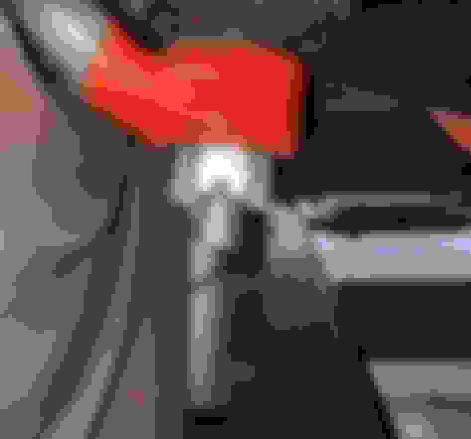
The upper and lower ball joint castle nuts have been timed and torqued properly, and as you can see in the pictures above, the cotter pins are in place but not bent because:
I�m not 100% sure which way to bend them. The reason I�m not 100% sure how to bend the cotter pins is because of the information I see in the AIM at the front of the manual and the information I see in the AIM in the front suspension section � showing 2 different ways to bend the cotter pins. Rather than taking a 50/50 chance I stopped the installation to ask for help. I�ll admit that I�m a greenhorn and that I�m probably just confusing myself needlessly as I should probably just bend the cotter pins as shown in the AIM. But, I�m not sure if the cotter pins for BOTH the upper and lower ball joint castle nuts get bent as shown in the AIM.
QUESTIONS:
Do the cotter pins for the upper ball joint castle nuts get bent as shown in the AIM?
Do the cotter pins for the lower ball joint castle nuts get bent as shown in the AIM?
Additionally, I�m not 100% sure that I�ve inserted the cotter pins from the correct side. As you can see in the pictures shown above I have inserted the cotter pins from the outside (tire side) of the car pointing inward toward the motor.
QUESTIONS:
Are the cotter pins supposed to be inserted in a specific orientation i.e. from the outside (tire side) of the car pointing inward toward the motor?
If you are able, are you supposed to insert the cotter pins with the flat side of the cotter pin adjacent to the nut?
Thanks for helping me to learn more about this subject. [img]file:///C:/Users/PREFER~2/AppData/Local/Temp/msohtmlclip1/01/clip_image001.png[/img]
Brian
Let me explain why I'm confused... When looking at the judging guide (most recent iteration) I see and read the following pieces of information:
Ball Joints... Ball joints taper down without threads at the lower end of the shaft that are secured to the bottom boss of the spindle using natural castle nuts and cotter pins that are not bent down, rather, when place into the pre-alignment device at the factory, they were bent upward to follow the contour of the attaching hardware. [ C 7-1 ]
[ C 7-1 ]
Is it safe to presume that the paragraph highlighted above in yellow is talking about the cotter pin for ONLY the lower ball joint?
Picture [ C 7-1 ] doesn't show how the legs of the cotter pin for the lower ball joint are bent, but I presume that they are bent upward (toward the upper ball joint)???
Picture [ C 7-2 ] on the other hand shows quite clearly how the legs of the cotter pin for the upper ball joint are bent but this picture completely conflicts with the text circled in yellow above from the Judging Guide.
If I had to interpret the information in the AIM and the judging guide and make a decision how to bend the cotter pins for the upper and lower ball joint castle nuts, I'd say that both legs of the cotter pins should be bent away from the ends of the spindle and therefore over the adjacent surface of the castle nut.
Am I interpreting this information correctly? Or do you bend the legs of the upper ball joint cotter pins differently than you bend the legs of the lower ball joint cotter pins?
Thanks for the education. I'm hoping that this post may help clarify this matter for those who come behind me confused about the same thing.
From my NCRS regarding suspension castle nuts - " secured with cotter pins with both fingers bent upward, following the contours of the attaching hardware"
Expand your yellow box to enclose the whole paragraph in the JG, then do as it says. It applies to "upper and lower ball joints". It matches the AIM, and don't worry about the photo in the JG. Do it the same for both upper and lower. You're over thinking this.
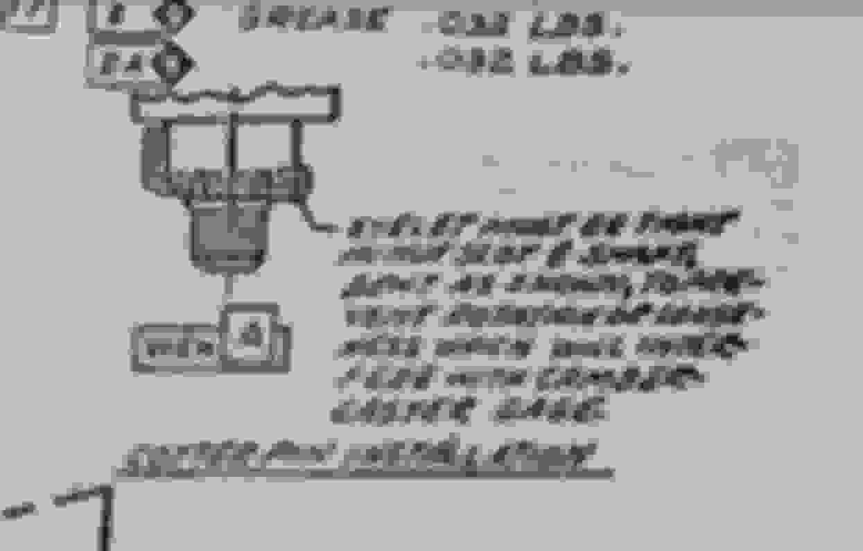
Hi, I will add that in the beginning of the 66 AIM it shows castle nut cotter pin installation
I have included a photo from the manual. So are both ways correct
Bob
The illustration at the beginning of the AIM is for normal cotter pins and castellated nuts installations, NOT those on ball joints. The alignment fixture put the unique bend in the ends of the cotter pins. Apparently ball joints is one of the exceptions noted.
 03-21-2021, 04:23 PM