When you click on links to various merchants on this site and make a purchase, this can result in this site earning a commission. Affiliate programs and affiliations include, but are not limited to, the eBay Partner Network.
Accessory wiring and suggestions for engine compartment buss bar/power distribution
Hey all.
I am going to be running both an electric cooling fan as well as electric headlight motors which will all obviously need power. I have read lots of suggestions of running this directly from the alternator (with the obvious fuses/relays) and so it would seem that rather than run multiple leads from the alternator that a buss bar or power distribution block would be a great idea so I can run a single additional lead to it from the alternator and distribute power from there.
I must assume that others have done this. Can you make a suggestion of a brand/model to use for this? Most of the products that I have seen state a 15a per circuit max which will not be enough for some cooling fans (I think).
Anyway, I am planning on running something like this:
Painless sells an auxillary seven circuit fuse box, that needs no assembly and just a power terminal from the battery. I mounted mine on the passenger side firewall. As far as the fans, the relays run off've the auxillary fuse box but the power to the relays comes from the battery. The two post terminal is pictured above and I ran a heavy 16 gauge wire, straight from the battery to one side and then other side, went to the aux fuse block (or box). Works really well! The cover even comes with a label underneath, with blank spaces to write what wire or circuit went to what. Document this too on a piece of 8x11 and put it in your FSM, you'll want to know this later.
Because firewall space is really sparse in these cars, I carefully mapped out and planned where these devices would be. Also, this makes it easier to manage the wiring, along the back of the engine compartment. When you're doing the crimps, I highly recommend using the 3M electrical crimps, a Matco Wire Stripper and a Matco heavy duty crimper.
The battery is like a bank account- the alternator is the income. You want big payments to come out of the bank account.
The battery does more than start your car- it stabilizes the voltage surges and filters the AC ripple left unfiltered by the alternator.
PLUS when the fans kick on- it's dang close to a dead short to get the blades spinning. That's usually when the car is at idle and the alternator is not putting out anywhere near it's rated power. The battery solves that problem as it has several hundred amp available.
I'd also recommend a PWM to power the fans- it's a lot lot nicer to the electrical system- as it soft starts the fans- sort of like a clutch dump at 3000RPM versus a rolling start.
I'd run a nice size wire -6 GU from the starter to the alternator- and another wire upfront near the source that will use the power,
For the big stuff- I like nice terminals with one of these types of fuses-Marine Rated Fuses
With that fusebox and 6 relays- you can configure a lot. Can use the relays for the headlights- have switched ignition sources and hot at all times. Lots of options.
I've shown the starter as a terminal block so to speak-
2020 Corvette of the Year Finalist (performance mods)
2019 C3 of Year Winner (performance mods)
2016 C3 of Year Finalist
I have a battery disconnect on the bulkhead between the seats. I takemy main power for my headlight relays and fan relays off the battery wire at the starter. I wired in the switched power for the fan relay off my wiper power. Tthe new headlights harness plug directly into the old headlight harness for thd relay trip. And both main power lines go through a self resetting breaker mounted to the inner fender. The system works great and its wrapped in with original harness so it blends in
For my cabin accessories like gauges, MSD , radio, antenna, and such I added a seperate fuse panel that lights up when a fuse blows. For the subwoofer and amp, they have their own fused wire directly from the battery .
Illl post pics later but the idea was to limit long runs of wire where possible
Last edited by Rescue Rogers; 04-23-2019 at 12:17 PM.
Painless sells an auxillary seven circuit fuse box, that needs no assembly and just a power terminal from the battery. I mounted mine on the passenger side firewall. As far as the fans, the relays run off've the auxillary fuse box but the power to the relays comes from the battery. The two post terminal is pictured above and I ran a heavy 16 gauge wire, straight from the battery to one side and then other side, went to the aux fuse block (or box). Works really well! The cover even comes with a label underneath, with blank spaces to write what wire or circuit went to what. Document this too on a piece of 8x11 and put it in your FSM, you'll want to know this later.
I really appreciate all of the suggestions and ideas...and your engine bay looks really tidy by the way! Great job! I like the idea of a painless system but since I am running so many items which will require relays, I kind of like the idea of having them all together. I will see if they make a 6 relay system like the one you posted.
Originally Posted by Richard454
Here's what I would do- and why....
The battery is like a bank account- the alternator is the income. You want big payments to come out of the bank account.
The battery does more than start your car- it stabilizes the voltage surges and filters the AC ripple left unfiltered by the alternator.
PLUS when the fans kick on- it's dang close to a dead short to get the blades spinning. That's usually when the car is at idle and the alternator is not putting out anywhere near it's rated power. The battery solves that problem as it has several hundred amp available.
I'd also recommend a PWM to power the fans- it's a lot lot nicer to the electrical system- as it soft starts the fans- sort of like a clutch dump at 3000RPM versus a rolling start.
I'd run a nice size wire -6 GU from the starter to the alternator- and another wire upfront near the source that will use the power,
For the big stuff- I like nice terminals with one of these types of fuses-Marine Rated Fuses
With that fusebox and 6 relays- you can configure a lot. Can use the relays for the headlights- have switched ignition sources and hot at all times. Lots of options.
I've shown the starter as a terminal block so to speak-
Thank you for taking the time to respond to this, Richard. I was hoping you would chime in as I know this is your wheelhouse. Your picture reminded me that I totally forgot to mention that will also be running halogen headlights and a MSD ignition system which is why I chose to go with at least 6 relays in the box.
Thank you again for the PWM suggestion. I really like the idea of this and did not even know it was a thing. I assume you are talking about the Derale model or are there others out there? I would appreciate suggestions from anyone who uses a PWM on which make/model to get.
I do have a question regarding the wiring (actually, several questions) but the first one that comes to mind is that you suggest that I draw power from the battery (which makes perfect sense). Would I then not way to run directly from the starter/battery cable to the PDU/fuse hold thingie that you are showing here? BTW What and where can I get that? What amperage fuses should I be looking to get to go on it? I am a little in the dark as to how to determine what the proper fuse rating should be for any given circuit. Is it simply the combined amp rating of everything drawing off of that circuit? I am certain that wire gauge must also play a part in that?
Finally, you mention having always hot and switched power through the supplemental fuse/relay box. How is that done? Always hot would obviously come directly from the battery/starter cable source...unsure about the rest.
Originally Posted by Rescue Rogers
I have a battery disconnect on the bulkhead between the seats. I take my main power for my headlight relays and fan relays off the battery wire at the starter. I wired in the switched power for the fan relay off my wiper power. Tthe new headlights harness plug directly into the old headlight harness for thd relay trip. And both main power lines go through a self resetting breaker mounted to the inner fender. The system works great and its wrapped in with original harness so it blends in
For my cabin accessories like gauges, MSD , radio, antenna, and such I added a seperate fuse panel that lights up when a fuse blows. For the subwoofer and amp, they have their own fused wire directly from the battery .
Illl post pics later but the idea was to limit long runs of wire where possible
Awesome! Thanks for all of this info and any pics would really be appreciated as I am also planning on running a sub and amp inside the cabin and was planning on coming directly from the battery.
Originally Posted by Kacyc3
I used a distrubtuion block from a caprice that is looking full and have been thinking about replacing it with a block from a 88-98 chevy truck.
Then a fuse center like others have listed for key on power not battery power. Mounting location has become the issue.
Thank you! I like the pic you have posted, it makes things nice and neat. I understand that firewall space on these cars is at a premium which is why I was figuring on mounting mine somewhere on the wheel well or inner fender area. Is that a bad idea? Other than a little extra wiring length, is there a downside to doing this?
Originally Posted by Rescue Rogers
My second fuse panel has a relay off the original fuse blocks ACC plug to make it key on only
If you could detail that out a little bit for me, I would gladly buy you a beer or three =)
2020 Corvette of the Year Finalist (performance mods)
2019 C3 of Year Winner (performance mods)
2016 C3 of Year Finalist
I'll try and get those posted tomorrow night. I had a spare relay from another wiring kit and they are simple to wire in. I still have everything apart so It wont be a problem
Thank you for taking the time to respond to this, Richard. I was hoping you would chime in as I know this is your wheelhouse. Your picture reminded me that I totally forgot to mention that will also be running halogen headlights and a MSD ignition system which is why I chose to go with at least 6 relays in the box.
Thank you again for the PWM suggestion. I really like the idea of this and did not even know it was a thing. I assume you are talking about the Derale model or are there others out there? I would appreciate suggestions from anyone who uses a PWM on which make/model to get.
I do have a question regarding the wiring (actually, several questions) but the first one that comes to mind is that you suggest that I draw power from the battery (which makes perfect sense). Would I then not way to run directly from the starter/battery cable to the PDU/fuse hold thingie that you are showing here? BTW What and where can I get that? What amperage fuses should I be looking to get to go on it? I am a little in the dark as to how to determine what the proper fuse rating should be for any given circuit. Is it simply the combined amp rating of everything drawing off of that circuit? I am certain that wire gauge must also play a part in that?
Finally, you mention having always hot and switched power through the supplemental fuse/relay box. How is that done? Always hot would obviously come directly from the battery/starter cable source...unsure about the rest.
You are welcome-
I'm running the Derale piece- seems they have gotten their act together as far as the temp sensor - as the earlier ones were problematic. Summit sells it- so if I have a problem- they are easy to deal with.
It really depends how much mods you want to do to the wiring- just using the starter terminal is the easiest - cost effect and really doing more you are at the point of diminishing returns. Just run a 1/0 GU wire from the battery to the starter and you'll be good to go.
The terminals- search "Marine Rated Battery Fuse" the marine stuff seem to have much better quality than the car stuff out there
The 'battery terminal type fuses'- a 75A for the fans and a 50A for the fusebox should be fine.
As far as the fusebox outs- 20A for headlight motors- for the headlights you can use a circuit breaker (auto reset type) that fits in a fuse slot- 20A For the MSD - I'm thinking 10A- but check the owners manual.
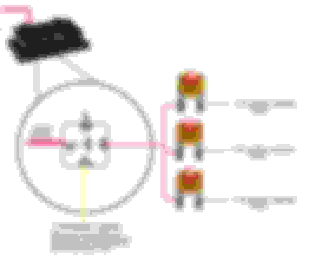
The relays-
You can have the battery power hot at all times go to a relay- and have the relay turned on by a ignition wire. see below
I really like using the "LED" blade fuse- light up when they are blown- WELL worth the few extra bucks!!!!
As far as switched sources- here's how it works at the ignition switch-
Here's what's going on at the harness on the firewall- since you are not using the CEC- you can use that wire as a switched ignition source
I'll try and get those posted tomorrow night. I had a spare relay from another wiring kit and they are simple to wire in. I still have everything apart so It wont be a problem
Thank you! I appreciate it!
Originally Posted by Richard454
You are welcome-
I'm running the Derale piece- seems they have gotten their act together as far as the temp sensor - as the earlier ones were problematic. Summit sells it- so if I have a problem- they are easy to deal with.
It really depends how much mods you want to do to the wiring- just using the starter terminal is the easiest - cost effect and really doing more you are at the point of diminishing returns. Just run a 1/0 GU wire from the battery to the starter and you'll be good to go.
The terminals- search "Marine Rated Battery Fuse" the marine stuff seem to have much better quality than the car stuff out there
The 'battery terminal type fuses'- a 75A for the fans and a 50A for the fusebox should be fine.
As far as the fusebox outs- 20A for headlight motors- for the headlights you can use a circuit breaker (auto reset type) that fits in a fuse slot- 20A For the MSD - I'm thinking 10A- but check the owners manual.
The relays-
You can have the battery power hot at all times go to a relay- and have the relay turned on by a ignition wire. see below
I really like using the "LED" blade fuse- light up when they are blown- WELL worth the few extra bucks!!!!
As far as switched sources- here's how it works at the ignition switch-
Here's what's going on at the harness on the firewall- since you are not using the CEC- you can use that wire as a switched ignition source
You sir, are amazing. Thank you so much for the detailed response, you have really taken all the guesswork out of it.
I also want to thank you Richard454 for freely sharing this info,,, all awesome ideas,,,, I got through my EFI-Fuel pump wireing ok, but it's nice to have a friend to call on for extra info,,,, All this info just went into my files for future reference, ,, , thanks again,,,,,,,,,,,,,,,,,teddy,,,
2020 Corvette of the Year Finalist (performance mods)
2019 C3 of Year Winner (performance mods)
2016 C3 of Year Finalist
here is how I'm setting up my auxiliary equipment fuse panel and my MSD box. THe hardest part is trying to get under the dash to run the wiring properly. Im only 5'10" barefoot and hovering below 190lbs so I'm pretty average and my elbows and hands all sliced up from rubbng on the dash and pedals. I took all these pics earlier tonight and then had a zip tie party cleaning everything up.....
The relays are wired the way Richard drew it up. I ran a line from the battery up along the drivers door sill, ( all my power goes on the driver side and all the readio signal going to the amp goes down the passenger side so there now static getting amplified. )
The power goes into the relay at blade 30 and it comes out the other side at 87 to the power lug on the new block. The block isnt grounded. The relay trip signal comes off the ACC blade and goes in the 86 blade. the ground side comes out the 85 to the birdcage
behind my dash running the LT blue power antenna line over to the stereo and the thin red line is MSD keyed on line going to the new fuse box
old fuse box with new style Blown Fuse Indicator blade fuses. I cant find those adapters anymore. Somone must have done something stupid with them and you cant get them anymore I guess. THe red wire going to the ACC blade in the center of the pic is the trigger for the realy to the new box
new fuse box mounted nexxt to the old box. I had to mount it side ways since there is no room under there because of the clutch. zthe back is sealed so Its not a hazard, theres just no room under there to put it any where and still be able to replace fuses
a view of the blown fuse indicators on the new block. All my new wiring has painters tape labels so I can draw a new wiring schematic on the back of my laminated one
power supply to the box is the big lug with te nut on it, I will either put a rubber boot over the bolt or cover it in RTV
kill switch mounted between the seats. Its not pretty but I can kill the car power if I have an electrical fire pretty quickly. I can just unscrew the handle and take it with me too if I get paranoid at a show
fuses for the amp and sub woofer
pretty huge blade fuses. The fuses and wiring all came with a subwoofer kit.
quick connect for trickle charger
trickle charger wire/ fuse and sub/ amp wires/ fuses
stereo setup, not much availble space with the top stored. I like how some peop;le hid theres in the storage compartments but I didnt want to get them too hot and I have my jack and tools in there anyway
roof down but still good sound. You can see the limitations.
this is the FM multiplexer behind the passenger side dash pad you can see its location. I removed it and mounted the MSD box there. These are older pics for reference.
this is the MSD wiring going through the firewall. I will RTV the openning closed
I had to mount it upside down so that the wires wouldnt interfere with the center bezel, it sits pretty far into the dash at that height. More wiring to zip tie and organize.....I put the box in here because I couldn't find anywhere in the engine compartment that would be functional and look good. At least it will stay cooler on this side of the fire wall as well
this is the fan relay mounted on the radiator support, the headlight relay is on the otherside. You can see the screws
headlight relays looking down along the hood
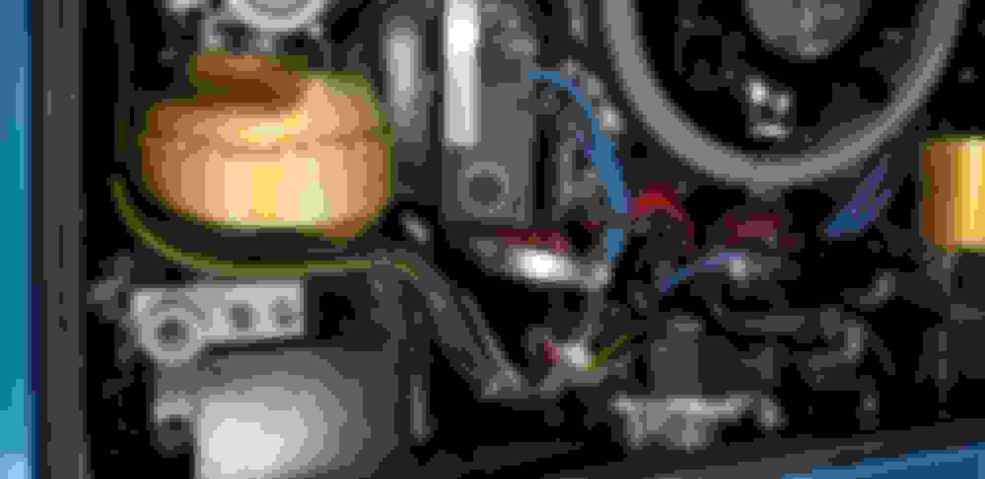
wiring hidden in with the vacuum hoses and original wiring. Those are the self resetting breakers. 30 amp each if I remembe. The green switch is on the ground wire going to the T stat for the fan. I can flip it to kill the fan if I need to have the key in the on position while working on something. wiring hidden in the original wiring run. THe MSD coil wires are sitting on the coil. it ususally had the shielding installed but I had to remove it to tighten the new oil pressure line
Last edited by Rescue Rogers; 04-24-2019 at 09:18 PM.
here is how I'm setting up my auxiliary equipment fuse panel and my MSD box. THe hardest part is trying to get under the dash to run the wiring properly. Im only 5'10" barefoot and hovering below 190lbs so I'm pretty average and my elbows and hands all sliced up from rubbng on the dash and pedals. I took all these pics earlier tonight and then had a zip tie party cleaning everything up.....
behind my dash running the LT blue power antenna line over to the stereo and the thin red line is MSD keyed on line going to the new fuse box
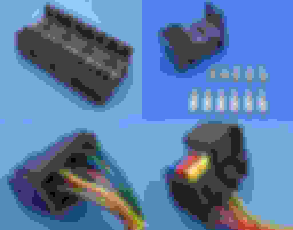
old fuse box with new style Blown Fuse Indicator blade fuses. I cant find those adapters anymore. Somone must have done something stupid with them and you cant get them anymore I guess. THe red wire going to the ACC blade is the trigger for the realy to the new box
new fuse box mounted nexxt to the old box. I had to mount it side ways since there is no room under there because of the clutch. zthe back is sealed so Its not a hazard, theres just no room under there to put it any where and still be able to replace fuses
a view of the blown fuse indicators on the new block. All my new wiring has painters tape labels so I can draw a new wiring schematic on the back of my laminated one
power supply to the box. I will either put a rubber boot over the bolt or cover it in RTV
kill switch mounted between the seats. Its not pretty but I can kill the car power if I have an electrical fire pretty quickly. I can just unscrew the handle and take it with me too if I get paranoid at a show
fuses for the amp and sub woofer
pretty huge blade fuses. The fuses and wiring all came with a subwoofer kit.
quick connect for trickle charger
trickle charger wire/ fuse and sub/ amp wires/ fuses
stereo setup, not much availble space with the top stored. I like how some peop;le hid theres in the storage compartments but I didnt want to get them too hot and I have my jack and tools in there anyway
roof down but still good sound. You can see the limitations.
this is the FM multiplexer behind the passenger side dash pad you can see its location. I removed it and mounted the MSD box there. These are older pics for reference.
this is the MSD wiring going through the firewall. I will RTV the openning closed
I the to mount it upside down so that the wires wouldnt interfer with the center bezel. it sits pretty far into the dash at that height. More wiring to zip tie and organize
this is the fan relay mounted on the radiator support, the headlight relay is on the otherside. You can see the screws
headlight relays looking down along the hood
wiring hidden in with the vacuum hoses and original wiring. Those are the self resetting breakers. 30 amp each if I remembe. The green switch is on the ground wire going to the T stat for the fan. I can flip it to kill the fan if I need to have the key in the on position while working on something. wiring hidden in the original wiring run. THe MSD coil wires are sitting on the coil
WOW! All I can say is THANK YOU for taking the time to put together such a detailed response. This will absolutely help me out tremendously. Thankfully, my entire car is down to the bare fiberglass so I can wire everything up before putting it back together which is why I am asking these questions now. I want to build the harnesses outside of the car and then install.
2020 Corvette of the Year Finalist (performance mods)
2019 C3 of Year Winner (performance mods)
2016 C3 of Year Finalist
That would be awesome to be able to do. You can add extra fuse blocks and junctions exactly where you need them. Just keep in mind the other parts that need to fit into tight areas and if you are running headers or not so you dont get to close to the pipes in the engine compartment if you use the lower fore wall in the engone compartment. And also remember how many wire runs and and how little room there is behind your dash gauges. And did you take pics of where your big wire loom went behind the tach and speedo. Different years ran it different ways and its a good ole fun time getting the dash back together. PM or post up if you want any other pics. Its not a problem, I'm sure others will post the fun they had behind the dash....
old fuse box with new style Blown Fuse Indicator blade fuses. I cant find those adapters anymore. Somone must have done something stupid with them and you cant get them anymore I guess. THe red wire going to the ACC blade in the center of the pic is the trigger for the realy to the new box.
Yep- I don't think anybody makes those anymore.
Here's another neat product- Modular fuse & relay- I'm up tp about 20+ in my car!!! I used three of them to replace my fusebox...and moved it to the kickpanel to make fuse replacement possible with out being a gymnast!!!
Here's a neat tool that will keep you from going insane- shrink tube labeler-
I think it's pretty neat, how we all approached this problem from different angles. I had room on the '74 firewall, because there wasn't a vacuum can for the wipers there anymore. My MSD box is actually mounted vertically on the passenger kick panel!

 04-23-2019, 10:37 AM