When you click on links to various merchants on this site and make a purchase, this can result in this site earning a commission. Affiliate programs and affiliations include, but are not limited to, the eBay Partner Network.
Quick question for Flyboy, a little off the subject. I wondered why my drive train looked off center when I installed it this week. The drive shaft is cocked off to the left a few degrees at the differential Now I know why. How does this affect drive shaft angularity? Pinion angle does the same thing, but up and down, not sideways. Does having the drive shaft angled in two directions have a negative effect, of is that normal in these Corvettes?
Quick question for Flyboy, a little off the subject. I wondered why my drive train looked off center when I installed it this week. The drive shaft is cocked off to the left a few degrees at the differential Now I know why. How does this affect drive shaft angularity? Pinion angle does the same thing, but up and down, not sideways. Does having the drive shaft angled in two directions have a negative effect, of is that normal in these Corvettes?
I apologize, but I am not at all educated on the science related to driveshaft angles. I have read lots of threads on this forum related to it, and you should search for those if you are interested. My recollection of this is that the angles built into the car by Chevrolet, in a stock configuration, are well within recommended angles. Its when you install aftermarket transmissions that this is a concern, and possible shimming and adjustments need made.
But as you pointed out, one thing I did not state in my long post on the facts of C2 and C3 Corvette design, is that the differential shaft connection is also offset to the right, which is obvious when you look at it, and makes sense that the engine, the crossmember holes, transmission rear mount and the differential attach point are all lined up. I believe I have read that the differential is not exactly one inch to the right, and there produces a small angle as you stated, ......but again, in a stock configuration has proven to be well within any limits and as designed by Chevrolet.
Thanks for your response. It seams logical that GM would not have created this offset if it was going to affect the driveshaft angles negatively. I wonder why they did it, though. Maybe someone more knowledgeable will chime in.
Went out to the shop, stared at it a while, and answered my own question. I first realized that the reason the drive shaft is off center is because the pinion gear is offset to the right because of the placement of the ring gear. In a conventional live axle differential, the axles are different lengths to compensate for this. On the independent suspension setup, the half shaft must be equal length so the pinion ends up offset to the right. So everything from the engine and transmission output shaft to the pinion shaft is offset 1.5" to the right. Once I realized this, I forced the transmission tail shaft to the left 1.5" and now everything lines up! Am I right C3 gurus?
Went out to the shop, stared at it a while, and answered my own question. I first realized that the reason the drive shaft is off center is because the pinion gear is offset to the right because of the placement of the ring gear. In a conventional live axle differential, the axles are different lengths to compensate for this. On the independent suspension setup, the half shaft must be equal length so the pinion ends up offset to the right. So everything from the engine and transmission output shaft to the pinion shaft is offset 1.5" to the right. Once I realized this, I forced the transmission tail shaft to the left 1.5" and now everything lines up! Am I right C3 gurus?
What do you mean you forced the transmission tail shaft to the left 1.5".......how?
What do you mean you forced the transmission tail shaft to the left 1.5".......how?
Loosen all the bolts on the motor mounts, and elongate the slots in the trans mount. Grab the trans tail housing and slide it left or right. Then tighten everything back down. I was only able to get about 1/2" of movement on my '73 BB. This is how I gained a little clearance when I installed the 1350 U-Joint up front.
John
Last edited by JohnRR; 05-31-2020 at 09:03 PM.
Reason: I hit "Enter" too soon.
I am not sure any of this forcing is required. I mounted the engine in the mounts at the front, as it pretty much has to sit in the cradle.....the rear mount holes were perfectly in line with the fore/aft slotted holes in the transmission mount, and the driveshaft connected to the differential where it was mounted. I know of nothing that suggests anything else is necessary. If anyone knows of something official, like in the Assembly Manual, or anywhere else, that suggests any additional checks or adjustments are necessary, please post it.
The car ran just fine for 16,000 miles after my restoration, no vibrations or any other indications that anything else needed done.
Don't want to second guess peoples actions, but are we possibly over thinking this issue?
I just meant I had to apply a little force with a bar to move it 1". As John stated, I loosened the motor mounts (which are brand new and stiff) and it went pretty easy. I am not working with a stock transmission, but a ZF six speed out of a '91 C4, so there are no mounting holes on the cross member for that trans. I had to fabricate a custom mount from an aluminum block in order to install it to the cross member. I ran a tight string between the pinion shaft and center of the engine to line everything up. Not overthinking, just trying to understand the reason for the offset.
I just meant I had to apply a little force with a bar to move it 1". As John stated, I loosened the motor mounts (which are brand new and stiff) and it went pretty easy. I am not working with a stock transmission, but a ZF six speed out of a '91 C4, so there are no mounting holes on the cross member for that trans. I had to fabricate a custom mount from an aluminum block in order to install it to the cross member. I ran a tight string between the pinion shaft and center of the engine to line everything up. Not overthinking, just trying to understand the reason for the offset.
OK, that makes perfect sense. I assumed you were working with stock components. I know well that when you stray from stock, there is lots of adjustments necessary.
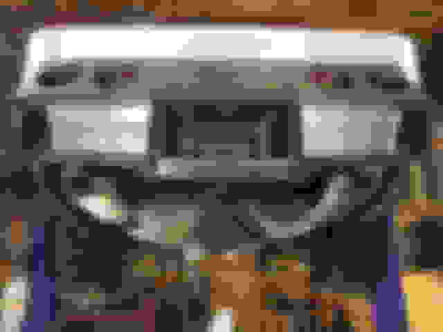
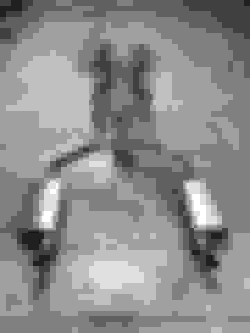
Currently working on another one-off stainless exhaust system. This time a '63 coupe on a Coffman chassis with an LS3 topped off with an LSClassic fuelie manifold. Here is a teaser.......I am now offering systems in brushed finish which some seem to prefer. Im liking it also.
Currently working on another one-off stainless exhaust system. This time a '63 coupe on a Coffman chassis with an LS3 topped off with an LSClassic fuelie manifold. Here is a teaser.......I am now offering systems in brushed finish which some seem to prefer. Im liking it also.
If Your still here I want to know more about the Belt Sander in this Photo !
Currently working on another one-off stainless exhaust system. This time a '63 coupe on a Coffman chassis with an LS3 topped off with an LSClassic fuelie manifold. Here is a teaser.......I am now offering systems in brushed finish which some seem to prefer. Im liking it also.
Do you need to have the car to build a setup? I have cast iron manifolds on a 72 small block. No headers but I'd like a full 2.5" setup
Sharing pictures of an exhaust system I recently built for a good customer. I have not found an aftermarket system that fit well so i began building my own for those who want quality.
This system is entirely 2.5" 304 stainless material, is tig welded, features stainless works turbo mufflers, and features an X pipe.
Anyone interested can message me for more info.
Thank you
Derek Oberlander

 05-29-2020, 10:47 AM