When you click on links to various merchants on this site and make a purchase, this can result in this site earning a commission. Affiliate programs and affiliations include, but are not limited to, the eBay Partner Network.
I've seen one pro and another amateur porter give up on the intake after they realized that. Doesn't matter how much you Siamese the runners, the 180deg turn will make any other design better than TPI
I know ... I followed Carnut1's thread on his 083 head and TPI adventures, over at SpeedTalk
I gave up also and went with this ...
But I still would like to flow the parts to see what is up
I bought a used SF-300 8-9 years ago for personal use only. What great hobby. I was heavy into Harley Davidson horsepower shootouts and Bonneville LSR's at the time. I acquired it to build a specialized sheet metal intake manifold and from there came port molds and area measurements to input into engine simulations to discover and solve issues I didnt I know I had. Seems to me that making and using a device in your intake runner can create a "Coanda Effect" in effect fix it. Experimentation is rewarding for sure.
I bought a used SF-300 8-9 years ago for personal use only. What great hobby. I was heavy into Harley Davidson horsepower shootouts and Bonneville LSR's at the time. I acquired it to build a specialized sheet metal intake manifold and from there came port molds and area measurements to input into engine simulations to discover and solve issues I didnt I know I had. Seems to me that making and using a device in your intake runner can create a "Coanda Effect" in effect fix it. Experimentation is rewarding for sure.
Years ago, long before the internet, there was a used equipment place that I would visit every other month.
Bought a lot of stuff there cheap.
One visit he had a SuperFlow bench and had cut the side open and pulled out all the vacuum pumps and wiring and sold them off, had no idea what he had and what it cost.
Man he wasn't happy when I told him
There wasn't anything left worth buying except the manometers, and then he wanted to much for them
I'm also more interested in the intake side for now, at this point in time you can buy better heads than I could ever port myself, fairly cheap
This is interesting and why I built this Flow Bench.
When I first flowed the Siamese runners against two AS&M runners they flowed just about the same, which doesn't make sense.
Wondered if it was a limitation of my bench airflow, but even though I can't flow all the way up to 28 inches H2O yet, I can still get good data bellow my maximum line.
Then I decided to flow just the adapter plate which is 3/4 inch thick and has two holes opened up to the gasket diameter.
It flowed less than it did with the runners installed?
It is looking to me like the flow rate is being determined by the smallest cross section area in the test, runners, length, bends don't appear to matter?
The runners actually helped the adapter plate flow a little more.
I opened up the adapter area to match the Siamese runners and the Siamese runners now flowed more, the adapter plate flowed more, and the AS&M runners stayed about the same.
So again the smallest cross section area in the intake track appears to determine the system flow rate.
Now ... what's the quickest way to mount this thing to my bench
I have a feeling that if the smallest area, choke point, is in the manifold, the runners aren't going to matter.
Just taking a guess on the adapter plate here but, running just the plate is like a sudden expansion/contraction vs like a nozzle with the runners. So it is possible they do help flow.
Just taking a guess on the adapter plate here but, running just the plate is like a sudden expansion/contraction vs like a nozzle with the runners. So it is possible they do help flow.
The calibration orifice plates that they lay on top the Flow Bench have a discharge coefficient of 0.62
The discharge coefficient of my orifice in a tube is working out to be 0.655, so it is a little more efficient with the tubes on either side.
The calibration orifice plates that they lay on top the Flow Bench have a discharge coefficient of 0.62
The discharge coefficient of my orifice in a tube is working out to be 0.655, so it is a little more efficient with the tubes on either side.
Don't know if there is any interest in something like this, but I decided my winter project this year is building a Flow Bench.
Always wanted one.
I'm buy no means a Flow Bench expert at this point, but I've been reading and learning.
Going to start by posting where I am now and if there is any interest, I'll back up and detail some of the build.
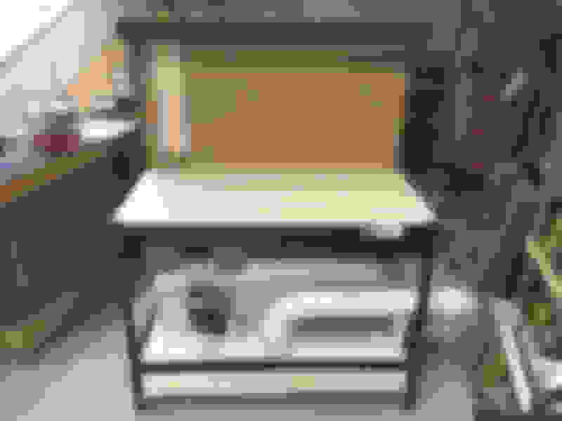
My bench today ... I'm in a dark spot of my shop, so pictures are a little difficult.
This is just starting out as a vacuum or flow thru bench, because that's what I'm most interested in.
I'll add a way to reverse flow, pressure test, say for exhaust ports later.
Started with a cheap Harbor Freight workbench for $110.
With the cost of building supplies now, don't think I could build one myself cheaper?
Starting with four 122 cfm vacuum motors. but left space to add two more.
I'll post more about the different ways to measure the flow rate in a later post, but I'll be measuring the pressure drop across a sharp edge orifice.
Most DIY Flow Bench builders have gone this way. and I have the ability to machine my own orifice plates.
One thing I've been dying to test is the different TPI runners.
I have some stock ones, Arizona Speed runners, and some SLP runners that I fully siamesed.
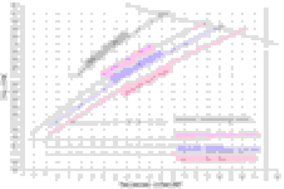
I flowed one runner and two together.
It surprised me that the siamesed runners flow about the same as the two ASM runners?
Stock TPI one runner 198 cfm
Stock TPI two runners 410 cfm
Arizona TPI one runner 257 cfm
Arizona TPI two runners 539 cfm
Full Siamesed SLP two runners 544 cfm
I intend on flowing the different runners with the manifold and plenum, as soon as I can build a fixture to hold them, and work out some calibration issues I'm trying to understand.
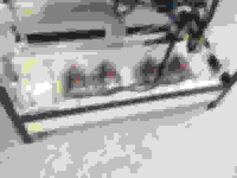
Made a quick adapter to mount the manifold with some scrap boards.
This is an Edelbrock TPI manifold, I don't have any stock manifolds floating around.
The intention is to flow the whole path manifold, runner and plenum.
I duct taped over the unused openings in the plenums.
I also fabricated a straight single runner to test as per a discussion a few posts back.
The plastic tube has an inside diameter of 1.61 inches, a little less than the AS&M runner at 1.67 inches.
The AS&M runners has an long side length of 11.5 inches and a short side length of 7.5 inches, so the middle length would be around 9.5 inches.
I cut my straight runner at 10.3 inches long.
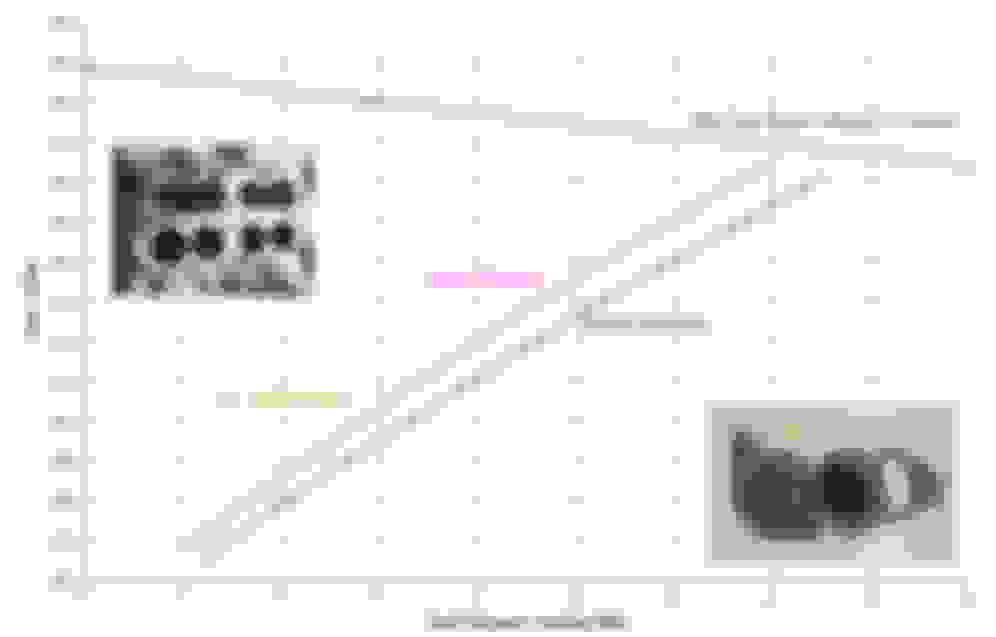
Was easily able to flow all combinations past 28 inches H2O.
I tested with cylinder #2 and plugged cylinder #4 for these tests, just flowed one runner.
Initially the Siamese runner looked pretty bad, flowing less than the AS&M, but you will see what happened on the next test.
The straight runner did outflow the nearly identical AS&M so that should answer the question about straight vs. curved runners.
The next series was with both the #2 and #4 runners open.
Now the Siamese runners outflows the AS&M runners, but why?
I don't have enough power in the bench yet to pull all the way to 28 inches H2O, so I corrected the tests to 28 inches and divided by two to get the single runner flow rates for this series.
Could not test the straight runner, only one runner.
Here is what's interesting.
The Siamese runners didn't flow more on the second test series, they flowed the same in both tests.
The Stock and AS&M runners both flowed less with two runners open?
I think the two runner openings, being so close together, interfere with each other trying to breath the same air from the plenum.
With the Siamese runner, even though the second runner #4 opening was blocked off in the first test, it must still be messing up the flow in runner #2.
I can't picture the flow when both Siamese runners are open?
I'm still letting all this sink in
BTW ... I picked cylinders 2 & 4 to test because they seamed to have the best position in the plenum.
Right in the middle, no tight turn from the throttle and plenty of space to draw from.
I bet cylinders 6 & 8 have even worse sharing problems.
I'll go back and test the four positions at some point this winter.
I have a stock '89 TPI assy sitting in the "museum", if you want to talk about shipping, you could have it for a while and try it out.
The straight pipe test was a great idea. I didn't really believe the claim about the 180* bend. The supporting video didn't pass the "gut check test" (for me), but I'm no flow bench guru...that's for sure. But you test tells the story; the ASM curved runner flowed ~3% less than the straight pipe. I'd expect a slight loss of flow w/a curve....and that is what you got. I don't see ~3% being "turbulence" and "air flowing in the wrong direction" in the tube, like the video claimed. Maybe, but I'd chalk it up as: "fairly meaningless" and "not why TPI sucks".
I've always understood TPI to "suck" due to:
1. Cross sectional area of the stock base and runner's and much more importantly,....
2. The resonant frequency of the runners -the runners' length.
I LOVE what you're doing and posting here. This is incredibly meaningful forum contribution.
Another interesting thing...
If the straight runner loses as much as the AS&M runner when paired with another flowing runner, it would flow the same as the Siamese pair.
That means the Siamese runners flow as well as a straight runner.
Not as bad as they looked at first
Originally Posted by Tom400CFI
I have a stock '89 TPI assy sitting in the "museum", if you want to talk about shipping, you could have it for a while and try it out.
The straight pipe test was a great idea. I didn't really believe the claim about the 180* bend. The supporting video didn't pass the "gut check test" (for me), but I'm no flow bench guru...that's for sure. But you test tells the story; the ASM curved runner flowed ~3% less than the straight pipe. I'd expect a slight loss of flow w/a curve....and that is what you got. I don't see ~3% being "turbulence" and "air flowing in the wrong direction" in the tube, like the video claimed. Maybe, but I'd chalk it up as: "fairly meaningless" and "not why TPI sucks".
I've always understood TPI to "suck" due to:
1. Cross sectional area of the stock base and runner's and much more importantly,....
2. The resonant frequency of the runners -the runners' length.
I LOVE what you're doing and posting here. This is incredibly meaningful forum contribution.
The thing about Darin Morgan is that he lives in a different world than us.
In Pro Stock and 9000 rpm engines every little thing matters, to us 400 horsepower 6000 rpm people ... not so much.
But we can still learn from them and see how it applies to us.
When I add more motors to my bench, I am going to rerun these tests at some very high pressure drops and see if the curve hurts more at higher velocities.
I stay away from all the arguments about wave tuning manifolds.
A simple way I look at wave or harmonics tuning is that it's just a narrow band supercharger.
Just like a small turbo adds boosts down low and a big turbo boosts at higher rpm, harmonic tuning adds boost over a narrow rpm range.
It won't ever reduce or take away power.
I agree that it's just area and length, 200+ CFM's just doesn't flow enough to make power
I'm pretty sure that tuned intakes DO hurt power outside of their tuned range. In one range, they boost cylinder pressure....outside of that range, they reduce it (compared to an un-tuned intake, or one tuned entirely outside of the operating range.
I believe that is why the TPI is so bad at ~4500 and up; at that RPM or so, the intake is out of phase with the engine RPM and "negatively" tuned for that range.
On another note, I have no idea why the ASM runners flowed worse w/no plenum, "open"? Other than the shapes of their mouths w/o the plenum there?
Just now getting a chance to read through this thread. It's really interesting and I'm glad SuperL98 is sharing his experiments. However, I do cringe when I see that the first thing he's testing is the TPI intake, because the one thing that makes it so awful is the one thing you can't test on a flow bench. I'm glad you did the straight-tube test so we could dispel the notion that the curved runners are the biggest problem with this intake. We can look around at other engine parts and realize that this isn't true: if it were true, then most head ports and headers would be completely hobbled by reversion because they have sharper turns than those TPI tubes. But you have given us direct evidence, and that's always the best.
But Tom already hit on the real problem with TPI intakes:
Originally Posted by Tom400CFI
I'm pretty sure that tuned intakes DO hurt power outside of their tuned range. In one range, they boost cylinder pressure....outside of that range, they reduce it (compared to an un-tuned intake, or one tuned entirely outside of the operating range.
I believe that is why the TPI is so bad at ~4500 and up; at that RPM or so, the intake is out of phase with the engine RPM and "negatively" tuned for that range.
They damn sure DO hurt power, and it's precisely because of that resonance effect. The mass of air in the any intake runner is accelerating and slowing in a harmonic pattern, and that resonance causes a periodic wave of increasing and decreasing pressure in the intake. Those harmonics are dictated by the frequency of the intake valve's opening and closing events. So it's totally dependent on RPM. At the RPM where you get the resonance in phase with the intake valve's opening event, you'll get extra air "packed" into the cylinder by the added pressure of the harmonic. On a TPI intake with its very long runners, that's at something like 3000rpm. So life is good at that RPM, where you get a mild supercharging effect. However, simple physics tells us that at 50% higher RPM than that - 4500rpm - the resonance will be 180-degrees out of phase with the intake valve. Instead of higher pressure that peaks when the valve is open, now you have the intake air pressure at its lowest point when the intake valve is opening, robbing it of air it would otherwise have if there were no intake runner at all. This kills power, and it's why all TPI and similarly long-runner intakes fall on their faces around this RPM.
The problem with a flow bench in this case is that it doesn't create any harmonics at all. It is a steady flow of air with no stop-start action caused by intake valves, so you can't possibly recreate the resonance that the intake has on an actual engine. Therefore, all the flow numbers you're getting for TPI-length intakes have no relevance to the power the intake can actually make. For example, it wouldn't surprise me if a full FAST TPI intake has twice the flow of a dead-stock TPI intake on a flow bench. And yet it's still going to crash and burn at a similar RPM to the stock intake because of the antiphase resonance, which means you still can't make much more ultimate power with it even though it flows so much better on the bench. OTOH, if you were testing something like a LT1 or Miniram intake, their runners are so short that their resonance isn't in the picture at any feasible RPM. Therefore, the flow numbers for that kind of intake would be meaningful.
Matt ... welcome to this thread and I am very aware of your views on wave tuning and the TPI manifold, and I value your input ...
The purpose of my thread is can I build a reasonably low cost Flow-Bench and I've reached the point that testing is the best way to decide how to move forward.
The TPI manifold is the perfect manifold to test my bench because it's not perfect.
It also has three distinct, easy to mix and match, sections to test together and individually.
It's also easy to modify, I made that straight runner in about a half hour.
Also a big plus for me ... I have a whole shelf full of these parts laying around.
And it's very C4 ... for the C4 section of the forum
I've learned that the airflow is very sensitive to how parts are mounted to the bench.
I've learned how sensitive the inlet side is to the test data, do I test with the sharp edge or radius it with clay, and what value is it if that clay is modifying the part?
Is it worth flowing the parts separate anyway, and not just test the complete assembled manifold first?
I'm learning if I have enough pumps to test what I want to, did I pick the right orifice size to measure with, do I need several orifices and an easy way to swap them around.
I learned that the manometers are a pain to read quickly and moved on to using digital gauges, but those need to be initially calibrated to the manometer.
I learned I need an Excel spreadsheet to do all these calibrations, calculations and graphs in real time.
I learned that two runners breathing the same air flow less than a separate runner does and to space them farther apart, if I ever tried designing a manifold.
Was using variable speed controllers a good choice to vary the pumps vs. running them flat out with an air bleed?
Does a Siamesed runner become part of the plenum volume, or does it still act like a runner ... starting to form an opinion on that based of what I am seeing.
Can I really correct data to 28 in H2O like everyone does and still call that result accurate?
I've heard some of the top head porters say they can tell a good port design just by the sound it makes on the Flow-Bench and I've notice that now also.
Some of the pieces, when flowed alone, make a horrible sound, my no loss calibration orifice sounds like a musical instrument.
I could go on ....
Why test a Wilson sheet metal manifold that's perfect ... it's perfect.
But now I'm starting to understand, just a little, why his designs are the way they are, buy looking at the imperfect.
After reading 20 years of threads about people battling TPI intakes, I have no delusions of discovering a secret to make it a great manifold ... I'm just using it to learn
[QUOTE=Tom400CFI;1604274581]I have a stock '89 TPI assy sitting in the "museum", if you want to talk about shipping, you could have it for a while and try it out. [/ QUOTE]
BTW .... Tom
Thank you for the offer, but I think anyone that has to stick with the TPI stuff, for emissions or whatever, would at least upgrade the manifold.
Far more interesting would be when you get to designing the plenum for your Cross Ram intake in your T-Ram thread..
With some accurate measurements, it would be relatively easy to build a single or dual channel replica of the manifold, out of plastic and cardboard, and try different plenum designs on it ... if I haven't lost interest in the whole thing by then, which I tend to do sometimes
Did anyone ever flow the stock CFI and the Renegade?
Quick internet search only comes up with vague numbers 170 to 190 CFM's for the stock manifold.
I think it's an interesting manifold and I would be cool to fool with one.
Tom (Buccaneer) did at some point but idk if the data was ever published. I have a ported one I can send and later on I'll have a stock one too and a kind of messed up renegade as well. The Renegade won't work on a car because of port alignment. I'll gladly work something out with you one day if you'd like.
 11-01-2021, 02:53 PM