When you click on links to various merchants on this site and make a purchase, this can result in this site earning a commission. Affiliate programs and affiliations include, but are not limited to, the eBay Partner Network.
Interfacing C6 Steering Wheel Controls to a C5 with Stock Clock Spring
Hey everyone, this is a project of mine which I've decided to make open source, mostly for the sake of my own motivation.
Recently I fitted a C6 steering wheel (with media control buttons) to my C5, but there's no way to interface these buttons to an aftermarket head unit while using a stock C5 clock spring. Yes, you could potentially use a C6 clock spring but that's not the point of this thread.
The solution I am sharing here is a device which utilizes wireless communication to bridge SW media controls over to an aftermarket head unit.
It's comprised of 2 separate units:
Master: car-side device which interfaces to head unit, and also hijacks the horn signal/power wire. As well it reads interior illumination information.
Slave: SW-side device which reads steering wheel buttons and horn switch.
Why?
I'm a Mechanical Engineer and perpetual tinkerer. I don't really do any programming/coding professionally so it's just a fun hobby that happens to be great for my personal/professional growth. This project gives me additional purpose for learning more about Arduino.
Currently there are 2 other Arduinos in my C5Z:
media control device which adds a physical **** to the button-less Joying head unit (sharing a good chunk of work from that project)
the C6 SW with media controls would replace this one
SWPS manipulator device that allows me to run an angle kit on my C5 while the Active Handling system operates & behaves normally
Stock C5 connects the horn switch signal through the SW via a mechanism called a "slip ring". It's 2 pieces of brass (one is spring-loaded) that rub each other while the SW turns. In addition, the SW itself acts as a ground and is effectively grounded to the chassis. I posted more details on this here
In stock form, the BCM sends ~12V power/signal through the slip ring to the horn switch. Pressing the horn shorts this out, passing about 140mA (0.14Amps) through the circuit. I'm thinking the SW-side unit will draw low enough current when idle that it can use this 12ish volts from the BCM temporarily (until the 2 units are wirelessly connected).
By hijacking the horn signal wire, I can send my own power through the slip ring to the SW-side unit so that it can be powered by a proper switched +12V source. With the other end of the hijacked wire I can simply short it to ground (with a relay that can handle 140mA) as needed to activate the horn.
Utilizing 2x Arduino "RF-Nano" boards, which are a combination Arduino Nano & nRF24L01+ board, the following happens:
Steering wheel side:
Constantly polls the steering wheel buttons for a resistance change (via a voltage divider)
Constantly polls the horn switch to check if it's being pressed
Does this by using a pullup input, where a horn switch press pulls the input to ground. Later I may look into using an interrupt instead but ultimately that level of speed is likely not required.
Any time a status change for SW buttons or horn occurs, it sends this to the Car-side unit
Car side:
Periodically polls the car's interior illumination, sends any updates to SW-side
There are 2 overarching conditions for this device:
When the car is off and/or the 2 units haven't established communication (or lose comm.), the units will revert to a default/disabled state where the horn system will operate like stock.
When both units are appropriately powered and communicating wirelessly, then SW controls will be granted, as well as buttons can be illuminated, and the horn will be able to operate seemingly normally.
To make these conditions possible, there are 4 separate relays across both units that control power, horn signal, and SW button backlights:
Master power relay: in default/disabled condition, this connects the car-side slip ring wire to the BCM's horn wire. When the relay is triggered (which happens after the 2 units establish communication), it sends +12V switched power through the slip ring to the SW-side unit.
Master horn relay: when triggered, this shorts out the BCM's horn wire, turning on the horn.
Slave slip ring / horn relay: under default condition, this relay connects the horn switch to the slip ring. When triggered, it sends the horn switch signal instead to the Arduino.
Slave illumination relay: simply sends +12V power (from switched source via slip ring) to C6 SW button backlights when told to.
Handling C6 SW media buttons and resistances:
SW-side: a voltage divider arrangement allows the Arduino to effectively read which button is pressed. I mapped out all this and listed it under the Figuring_out tab in my source code link.
Car-side: I came up with a resistor ladder arrangement that gets triggered by the Arduino, which will output different resistance values through a single wire. It's kind of a unique implementation that I developed for the Joying media control device.
These resistance values are intended to mimic the C6 SW media buttons. The idea being that you can use an off-the-shelf device that would normally translate C6 SW button signal to an aftermarket head unit. The Joying head unit I use has a learning function where I can teach it what each of the SW buttons does so no need for the intermediate device.
What are the current limitations?
My C6 SW doesn't have bluetooth control buttons so I haven't detailed those out (although there are placeholders for them)
The "RF-Nano" Arduino board I chose is becoming less available... no longer available on Amazon, and another US-based source I contacted suggested they might never be available again.
However, these boards appear very available on Aliexpress, and I just received several of them from a Chinese seller.
Compared to my Amazon-purchased units, the Aliexpress-purchased units seem to have 2 major differences:
2 of the wireless module pins are flipped, so they have to be flipped in the code when switching between the 2 different boards. It's not an issue, just an annoyance for when I forget.
Aliexpress ones use the "old" Arduino Nano bootloader while Amazon ones the "new" bootloader, so there's an extra configuration change needed when uploading code between the 2 different boards.
I've built up a breadboard of the 2 units and began preliminary bench testing. So far wireless communication is working well and I'm ready to hook it up to the car and proceed with further testing.
After the breadboard test concludes, I will build up the 2 units in a prototype form and package them to fit into the car, though currently I'm not entirely sure what that will look like.
If anyone has PCB design experience, I'd be thrilled to connect with you. As much as I want to learn basic PCB design (and may some day), I don't currently have time for it. But I can definitely do the 3D CAD packaging side.
The goal is to be able to provide boards at any stage of assembly, from bare PCBs all the way to completed units that are loaded with code and ready to wire up into your car. Not sure how to navigate this, though, since I'm not a Supporting Vendor and therefore can't actively list these for sale.
This is great, it's cool to see you taking a much deeper dive into the controls system than most of us have the knowledge or skills to do. I've been wanting to do a c6 steering wheel swap to get audio controls (for a joying head unit), but didn't even start down the path because of the class 2 serial data to CAN bus change from c5 to c6. If everything shakes out as you expect and you get to a point of making a batch of these, I'd definitely be interested.
This is great, it's cool to see you taking a much deeper dive into the controls system than most of us have the knowledge or skills to do. I've been wanting to do a c6 steering wheel swap to get audio controls (for a joying head unit), but didn't even start down the path because of the class 2 serial data to CAN bus change from c5 to c6. If everything shakes out as you expect and you get to a point of making a batch of these, I'd definitely be interested.
Fortunately, in general SWC (steering wheel controls) like this at their core are super simple: just changes in resistance values. What the C6 does with those resistance values is a different story and of course not applicable to the C5. Other guys who have used a C6 SW with working SWC just used a C6 clock spring, and then the SWC breaks out on a single wire (referenced to ground). Some head units may require a converter of sorts do go between the SWC wire and head unit, though that is just a remapping of resistance values and isn't related to digital communications like CAN. Some head units (like the Joying I have) offer learning features which can directly program the resistance values from a C6 SW.
Over the weekend I managed some progress: completed bench testing which included code changes to fix several errors, and I now have all the car's wiring ran to accommodate the 'master' side unit. That unit will go under the traction control button for ease of access, plus my existing Joying volume control device wires are already ran to that spot (I'm using 3 wires from that, plus 3 additional wires).
Originally Posted by MetalMan2
After the breadboard test concludes, I will build up the 2 units in a prototype form and package them to fit into the car, though currently I'm not entirely sure what that will look like.
If anyone has PCB design experience, I'd be thrilled to connect with you. As much as I want to learn basic PCB design (and may some day), I don't currently have time for it. But I can definitely do the 3D CAD packaging side.
Realistically I would spend A LOT of time coming up with a hand-wired perforated board circuit board (prototype units). Been there, done that with the other Arduino-based projects I listed previously.
It's cheap to have custom PCBs made if you can generate the PCB design. Soooo I decided to try out PCB design... one of the recommendations I keep coming across for a free design tool is EasyEDA.com . I had zero PCB design experience prior to this, other than working closely with electrical engineers who were doing it. And already I think I have a viable PCB for the 'slave' unit! The 'master' should be quick since I have a good grasp on using the EasyEDA online editor.
My biggest regret is not trying out PCB design sooner. I could have saved a lot of time in the long run.
Progress!
Over the weekend I tested various functions of the Master & Slave units and made a variety of code changes accordingly. Presently I'm happy with how things are operating. Wound up chasing my tail for a bit on a dumb breadboard ground issue but afterwards it was smooth sailing.
Then I finished up v1.0 of the Master & Slave PCB design/layouts. Last night I ordered qty 5 of each from a Chinese PCB vendor (they are the parent company which operates EasyEDA.com). Total was $16 shipped for 5 of each board which to me is SUPER cheap... I'll remain optimistic about the quality. Should have them in about a week.
China made PCBs came in the other day. I'm actually pretty pleased with their appearance, makes me think that they ought to have good quality.
Last night I started soldering everything. It went pretty quick since I put in so much effort up-front on the PCB design/layout. Unfortunately, as usual, I was in a rush and so didn't take any progress pictures. But I have enough parts to build up one more set so I can take more time and photograph the process.
My goal last night was to get the Slave unit installed into the steering wheel so I could drive the car again... airbag had been removed for the last 2-3 weeks as I played with the breadboard setup to make sure things were working (plus debugging Arduino code). That means I didn't drive the car for 2-3 weeks
Managed to meet my goal at the expense of a little sleep. Below is it installed in the C6 SW, turned out to be a great fit. Here the car-side BCM/horn wires hadn't been connected yet, so the Slave unit was unpowered. Also you'll note that the wires between Slave unit and C6 SW connector are a bit of a mess... it will all come out again in the foreseeable future and I'll sleeve the wires at that time.
Below is showing the Slave unit powered up after I connected the car-side BCM/horn wires together. This is a temporary measure until I get a chance to finish up the Master unit and get that installed (BCM/horn wires will go to the Master).
The Slave unit's default/unconnected state makes it so that the horn behaves like stock. So in the above picture the BCM is powering the unit, but pushing the horn still shorts out the horn wire like stock. Fortunately the horn works because I needed it when another driver almost merged into me!
I enjoy your projects. Reminds me of my much simpler foray into confirming that the HUD can be retrofitted to a non-hud equipped pre-99 C5. Or rewiring my LED tails a decade ago to turn them into halos. Always tip the tinker.
great ...So do I need to prepare myself to start to buy those board now so l can be ready for the next ?
Well, I have 4 extra board sets and currently 1 extra set of parts (more parts sets are easy & quick to come by). Let me know if you'd be interested in me building up boards for you.
Well, I have 4 extra board sets and currently 1 extra set of parts (more parts sets are easy & quick to come by). Let me know if you'd be interested in me building up boards for you.
All l need my steering wheel controls working with my Kenwood .. and yes I want you to build that for me ..you know we start together to change out OEM steering wheel C5 to C6. So we are in the same boat 😄
All l need my steering wheel controls working with my Kenwood .. and yes I want you to build that for me ..you know we start together to change out OEM steering wheel C5 to C6. So we are in the same boat 😄
But with the Arduino I can (theoretically) make the output whatever it needs to be for any different aftermarket stereo, so a converter box wouldn't be used. Making the change may just be a matter of using different resistors which is easy.
Some aftermarket stereos have a learning/programming feature for SW controls. My Joying stereo does, for example, so I can use the C6 SW button resistances as they are.
Originally Posted by WytNyt
This is impressive. You all are absolutely mind blowing. I'm dizzy but I'm learning! Following!!
But with the Arduino I can (theoretically) make the output whatever it needs to be for any different aftermarket stereo, so a converter box wouldn't be used. Making the change may just be a matter of using different resistors which is easy.
Some aftermarket stereos have a learning/programming feature for SW controls. My Joying stereo does, for example, so I can use the C6 SW button resistances as they are.
Thanks We're all learning!
l have Kenwood DNR876S. This one have one wire for steering wheel controls actually all the Kenwood have that and l use this one to control the volume wireless
https://axxessinterfaces.com/product/RFASWC
l have Kenwood DNR876S. This one have one wire for steering wheel controls actually all the Kenwood have that and l use this one to control the volume wireless
I'm not having much luck finding the resistance values to use for Kenwood stereo SW control wire. But maybe you can help with that... just need you to measure the resistance between SW control wire and ground when you press each button on your Axxess RFASWC remote. Do you have a multimeter?
I'm not having much luck finding the resistance values to use for Kenwood stereo SW control wire. But maybe you can help with that... just need you to measure the resistance between SW control wire and ground when you press each button on your Axxess RFASWC remote. Do you have a multimeter?
lwill get the multimeter tomorrow and test it .so one go to Kenwood wire steering wheel controls and the other go to the ground wire and lwill start to press each button to see the number ..
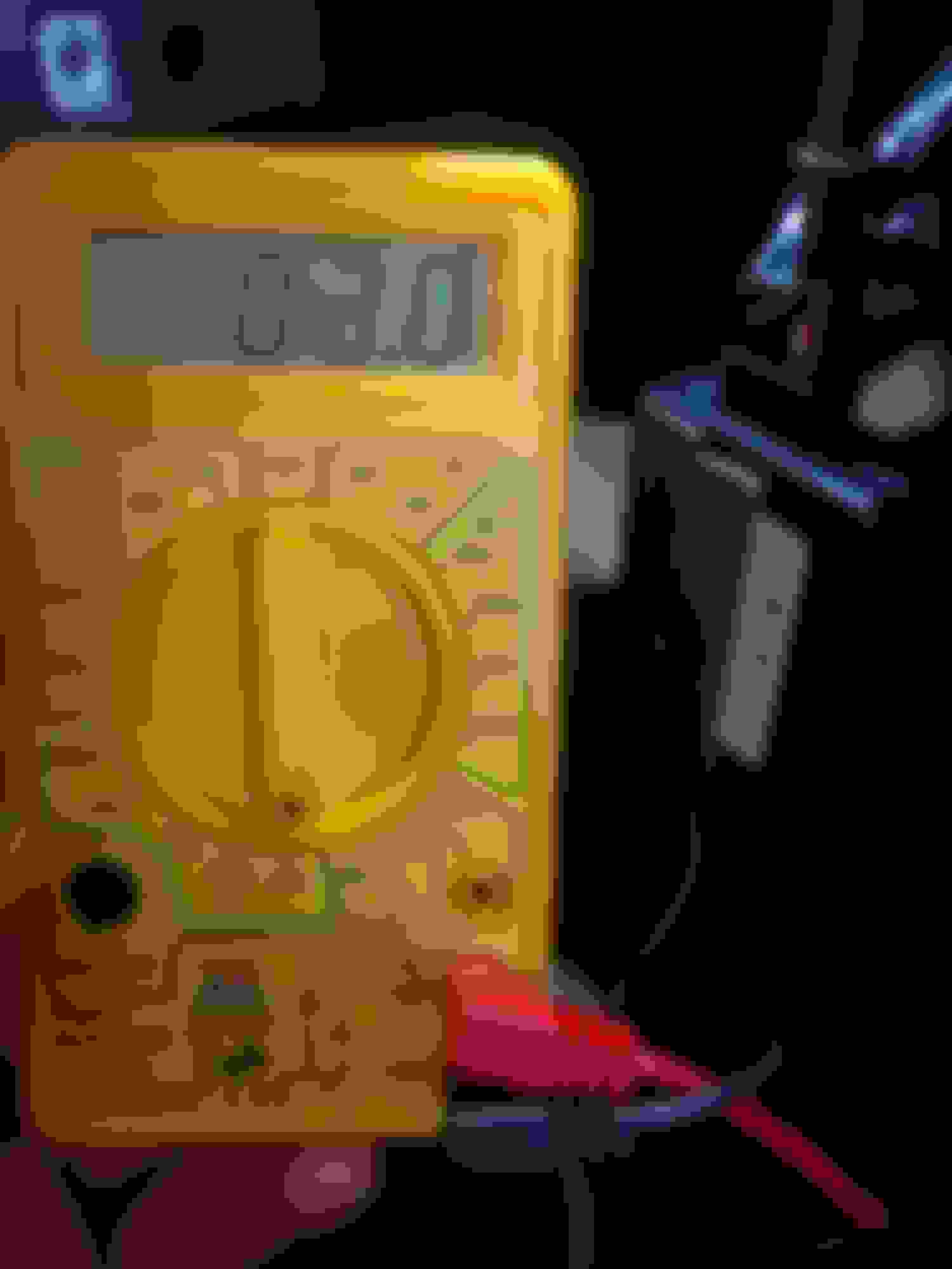
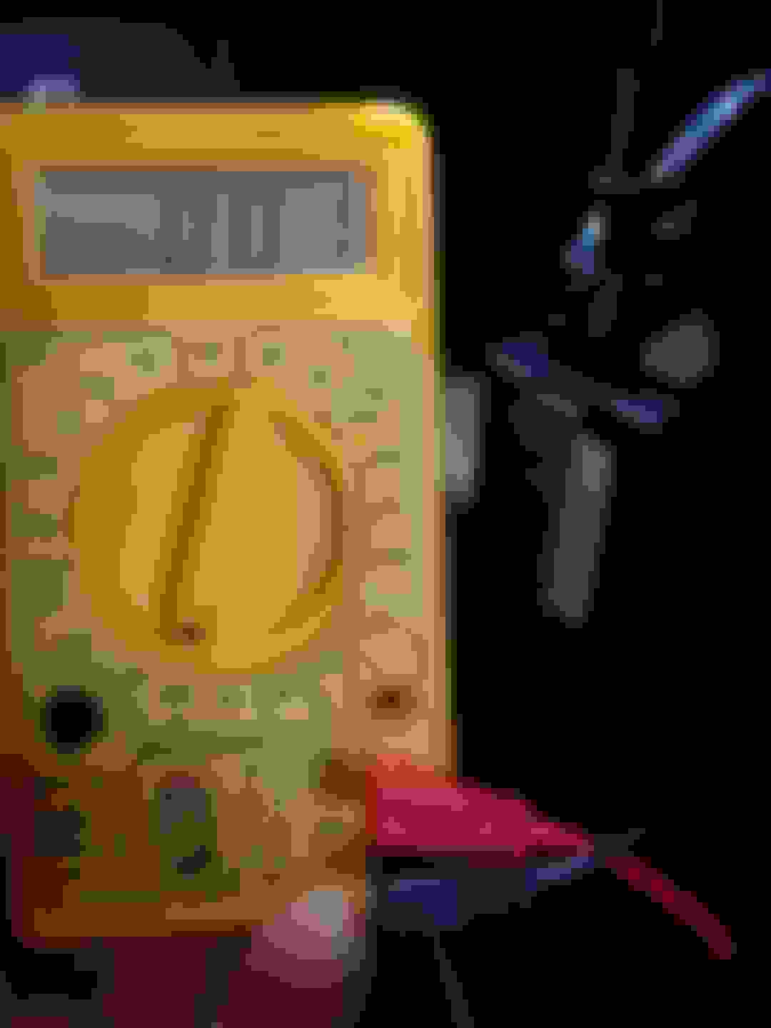
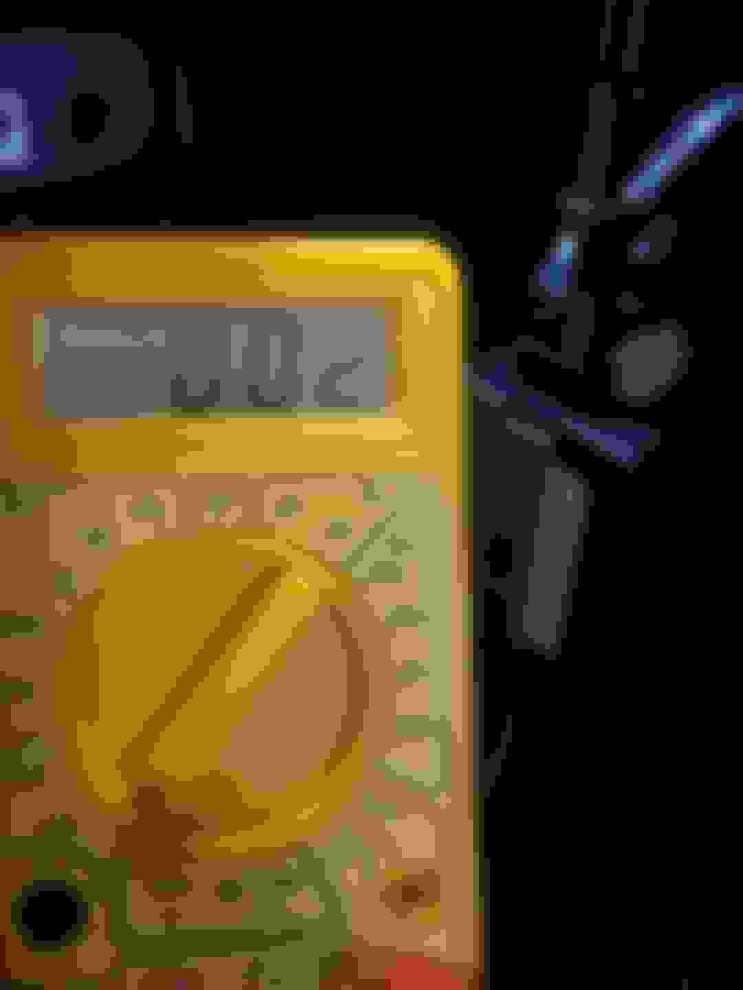
I'm not smart with multimeter but I try....the red side multimeter go to steering wheel controls wire Kenwood ( the same one connected with the black box Axxc )..the black side multimeter go to the skinny red wire the one coming from Axxc box and gave those reading without pressing any buttons ....if l put the black side to Axxc box ground nothing gave me no reading ... So those what l get with different options .. you decided Kenwood wire steering wheel controls connected same time with the black box Axxc Red wire the skinny one
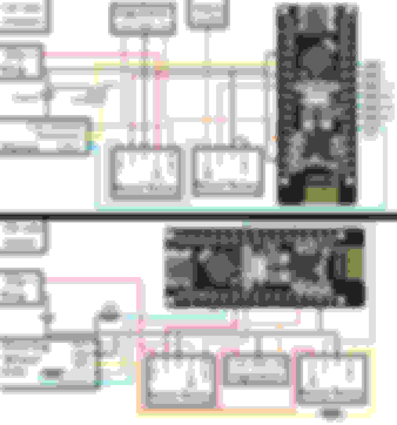
Got the Master & Slave working together nicely in my C5! Took a video (kinda long for what it is, sorry) and you can see it below. Also below are progress pictures of the 2nd set of boards I'm currently building up. (sorry for the poor quality pics, best I could get for whatever reason)
I'm not smart with multimeter but I try....the red side multimeter go to steering wheel controls wire Kenwood ( the same one connected with the black box Axxc )..the black side multimeter go to the skinny red wire the one coming from Axxc box and gave those reading without pressing any buttons ....if l put the black side to Axxc box ground nothing gave me no reading ... So those what l get with different options .. you decided
Kenwood wire steering wheel controls connected same time with the black box Axxc
Red wire the skinny one
If you set your multimeter to the 20k or 200k Ohm setting, is there a way you can get readings that are about 2k up to about 50k Ohms when you press different buttons?
For example, on a Pioneer stereo, these are the resistance values:
Volume up: 16k Ohm
Volume down: 24k Ohm
Next track / seek forward: 8k Ohm
Previous track / seek backward: 11.2k Ohm
20k setting on the multimeter means that it can read up to 20k Ohms, and you can read up to 200k Ohms on the 200k setting. With 200k setting it has less accuracy for the smaller resistance values.
Cool video. Common sense stay alive function. Handy joying tuning setup program. Making me want to look up my pioneer avic nex controls!
Not for nothing, but as you continue to enjoy these side projects and developing niche or one-off products I hope you're also keeping an eye towards secondary income producing batches of product on the side.

 07-28-2022, 02:12 PM


 We're all learning!