C6 Corvette: How to Install Aftermarket Navigation
Navigation receivers keep getting more user-friendly while adding new features. But what's involved with installing one in your C6 Corvette?
This article applies to the Corvette C6 (2005-2013).
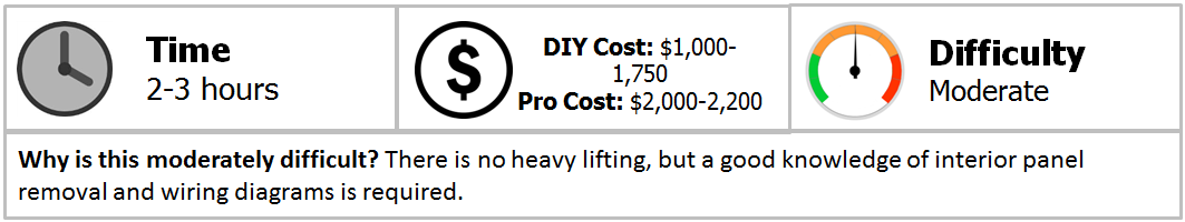
New navigation receivers include more than just directions for finding a restaurant or GPS guidance. There are many new aftermarket navigation receiver models available from numerous vendors. Some owners pick the unit based on its GUI, while others make their choice because of one or more additional features, such as touchscreen, voice activation, Bluetooth capability for hands-free calling, or even the ability to search through an iPod playlist. Popular brands for aftermarket in-dash navigation receivers include Kenwood, Pioneer, JVC, and Alpine, which cost from $1,000-1,500. You'll also need to purchase a complete interface kit, which goes for about $250. The professional cost includes $300-400 for labor, plus the markup on any installer-supplied materials and components.
Replacing your current radio or navigation system with a new aftermarket navigation receiver requires an interface kit. This job should only be attempted by those familiar with both removing (and replacing) automotive cowling/plastic panels, as well as dealing with wiring diagrams and splicing into and out of electrical plugs and harnesses. You might be better served using crimp-on type insulated plugs, taps, butt connectors and jumper wires to accomplish this, especially if you anticipate possibly removing the navigation unit and bringing your vehicle back to its stock showroom condition for future resale or trade-in. Simply unplugging your interface kit adaptations, then plugging the original unit back in will be a lot easier than having to refurbish the wires, plugs, and connections back to their original states.
Materials Needed
- Various-sized bits to remove small metric hex (Allen), star (Torx) and/or cross-point (Phillips) screws
- Molding and trim removal tools
- Small wire cutters
- Crimping tool for wire connectors
- File to reshape new navigation receiver's bezel into Corvette cowl opening
Like radios, navigation units are labeled as single DIN or double DIN in size, meaning about two or four inches in height. All units are approximately 7 inches wide, with screens ranging from 6.1 to seven inches diagonally. Chassis depth is also pretty standard among all the aftermarket units. C6 Corvette sound systems came in “base” or standard configurations and higher-end configurations labeled “Bose.” The Bose audio was somewhat unique in that it used an external in-line amplifier setup to drive its speakers, with the amps hidden in locations as the left side footwell. Accommodating a Bose sound system is best accomplished by purchasing an interface module and wiring kit specifically designed to handle GM with Bose systems.
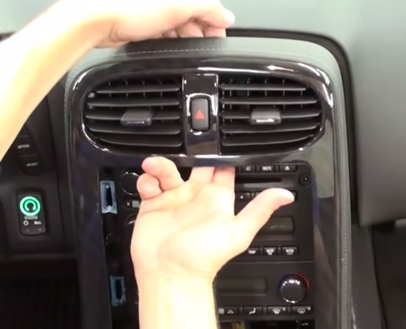
Removing the Console
To replace the factory radio or navigation system, you’ll first need to remove the console. A well-produced tutorial video is featured below these steps. Note that the point of this video was to replace the shifter, but in doing so it also shows how to expose the radio mounting cage.
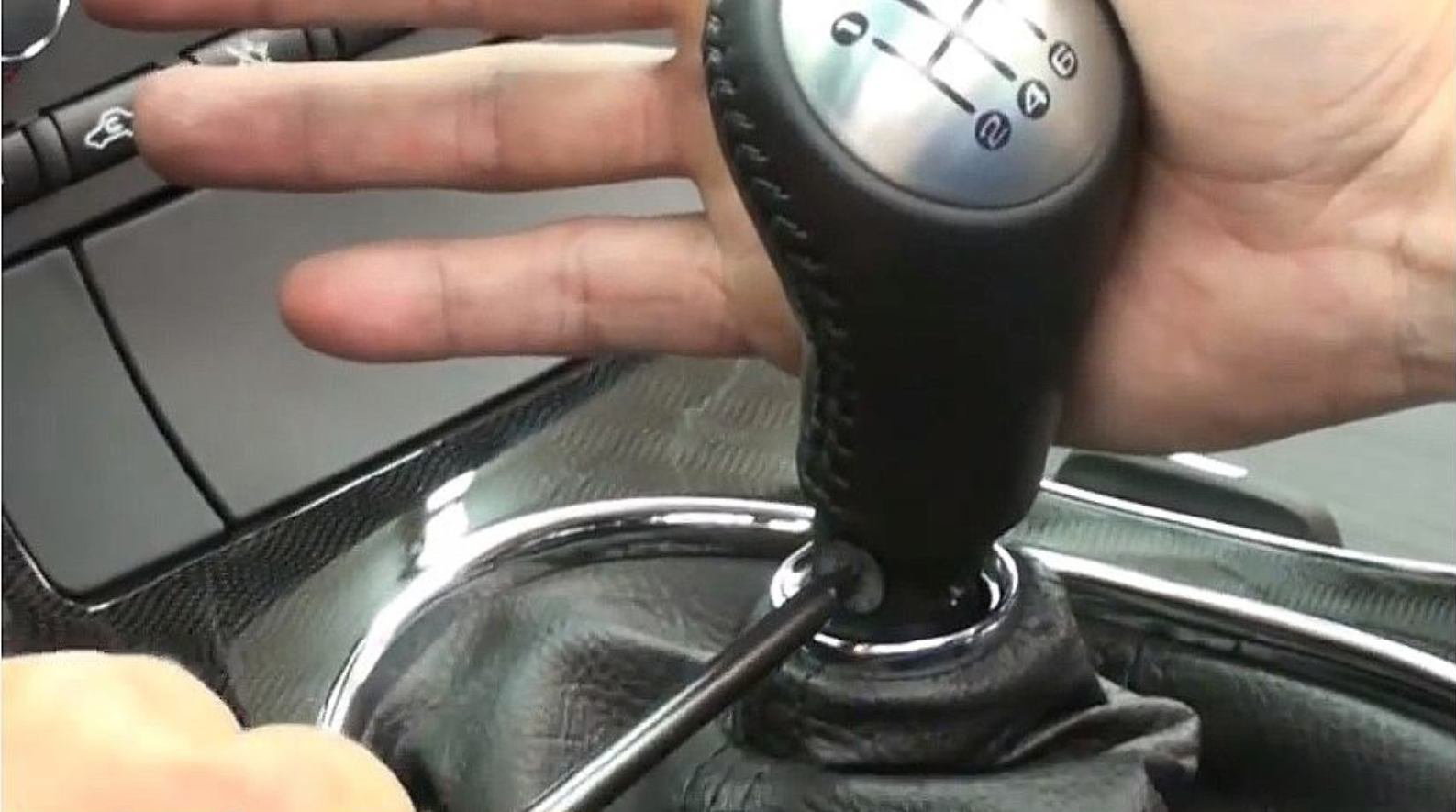
Step 1 – Remove the shift knob (optional)
First, lower the shifter boot and remove the shift knob, remembering to keep pressure against your wrench as thread lock was used on the T-20 attachment screw (shown in Figure 1 below). If you have an automatic transmission, you can skip this step, as the console lifts off the shift lever and gear selection indicator cleanly.
Step 2 – Remove the center console storage box lid
The center storage box lid is held on with a "piano-type" hinge by four T-15 screws.
Pro Tip
Do not over-tighten these screws when replacing this lid. Over-tightening could cause the screws to strip or break, making it very hard to remove and replace.
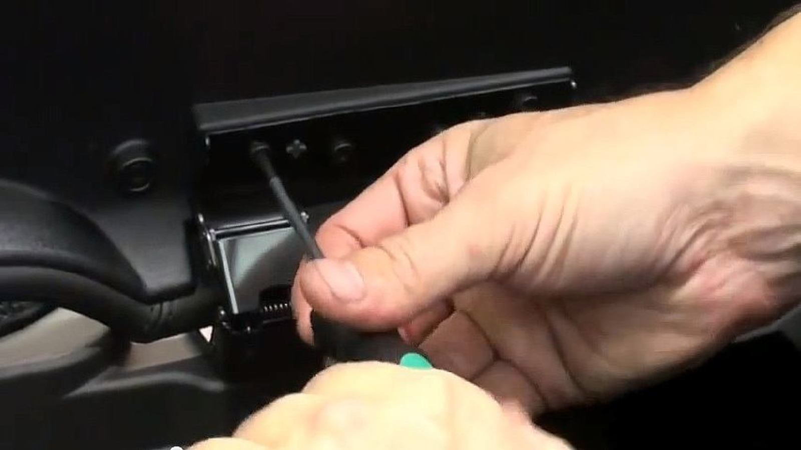
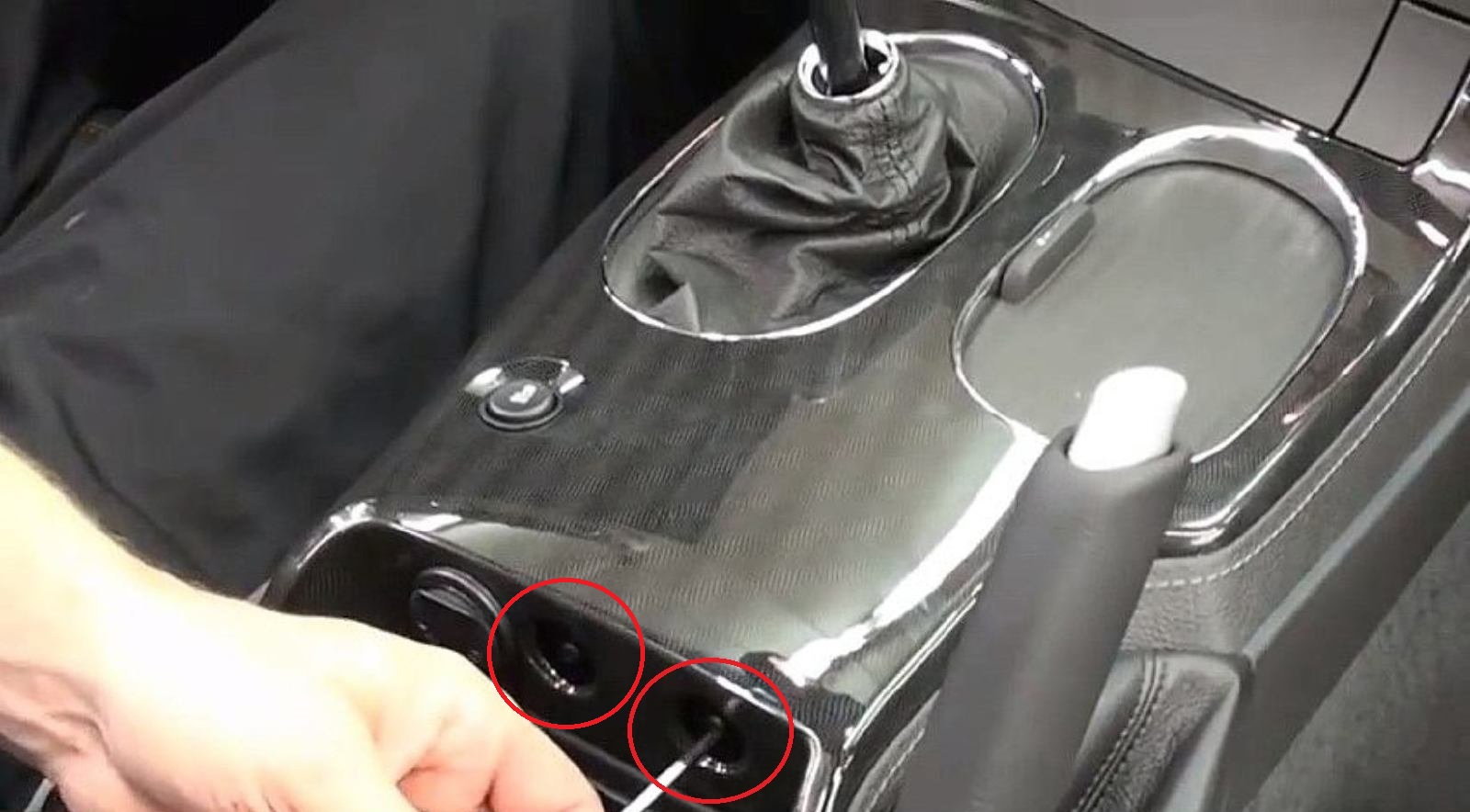
Step 3 – Remove the two front screws on the front of the storage box
Remove the round plastic covers, then extract the two 7mm T-15 screws on the front wall of the open storage box (as shown in Figure 3 below).
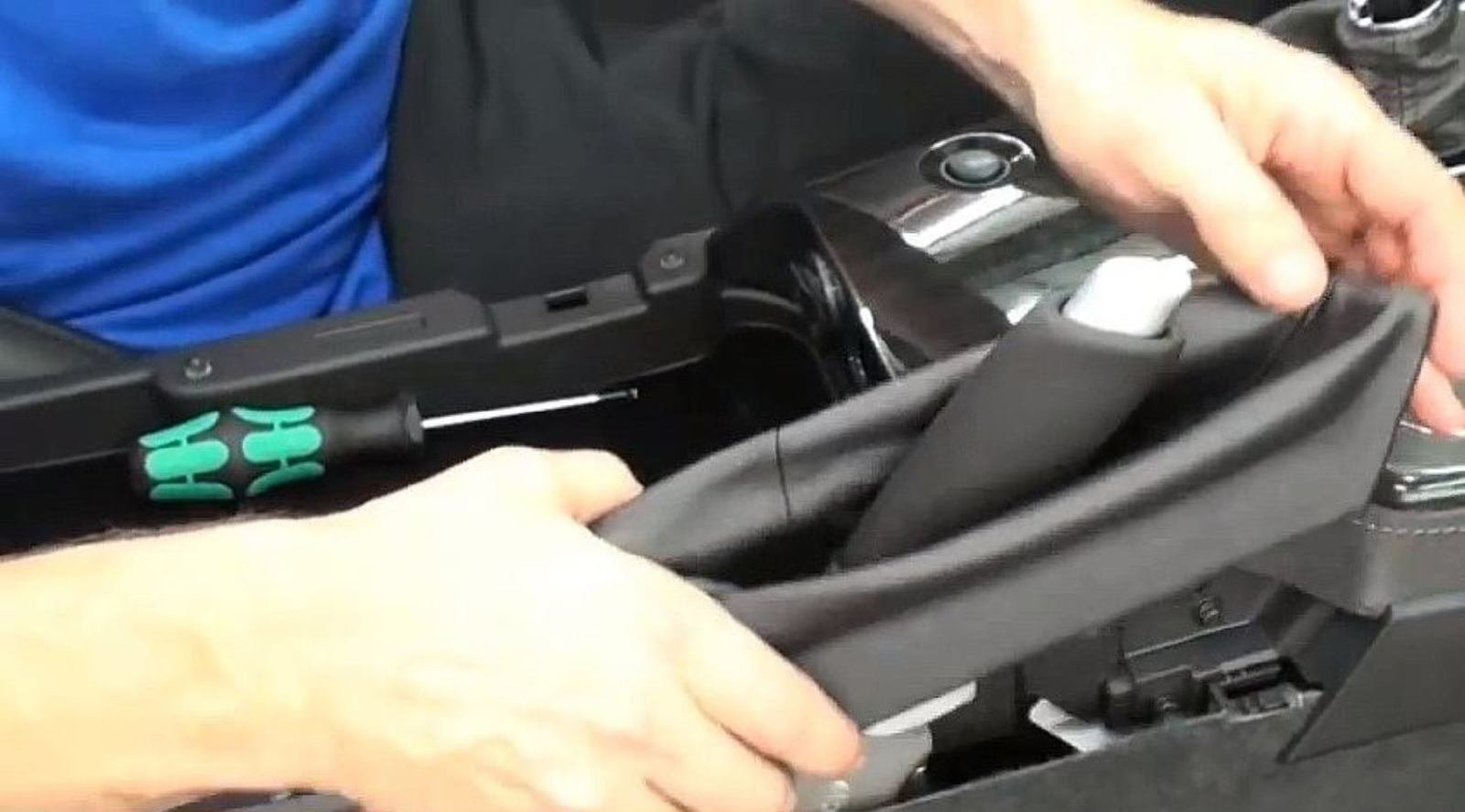
Step 4 – Un-clip the two clips holding the emergency boot in place
They are located at the top of this boot and on either side of the brake lever. This is done by carefully feeling out the clip locations and gently pulling up. Leaving it attached to the base of the handle, pull the boot up and over the top of the lever and drape it off to the the right, out of the way.
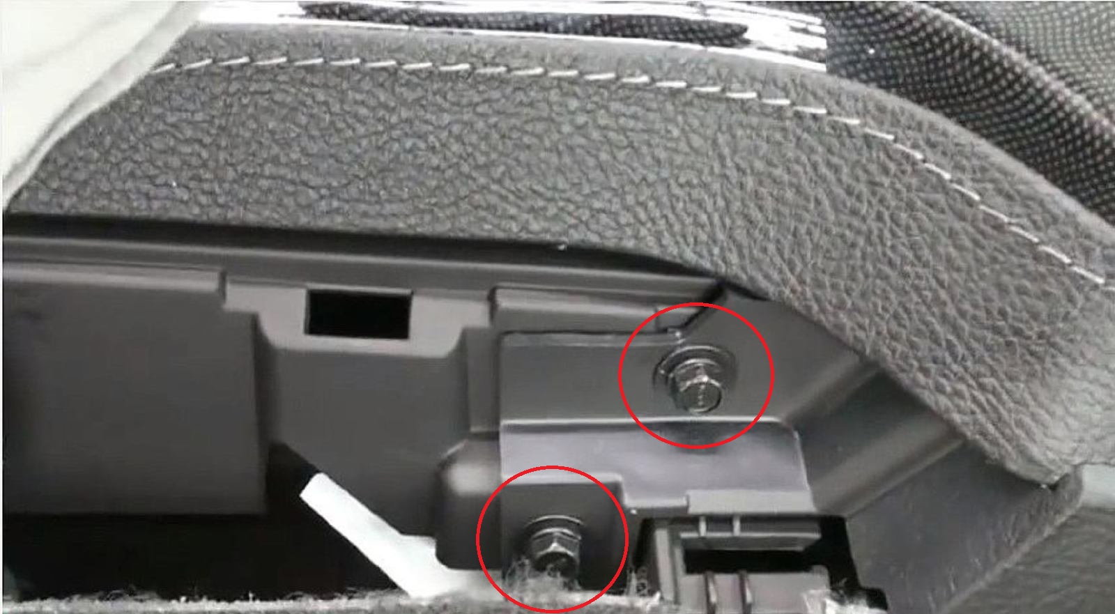
Step 5 – Remove the two bolts at the front of the emergency brake
Remove the two now-exposed 7mm bolts at the front of the emergency brake cavity.
Pro Tip
Be careful not to drop these bolts into the narrow cavity below or it will be very difficult to retrieve them.
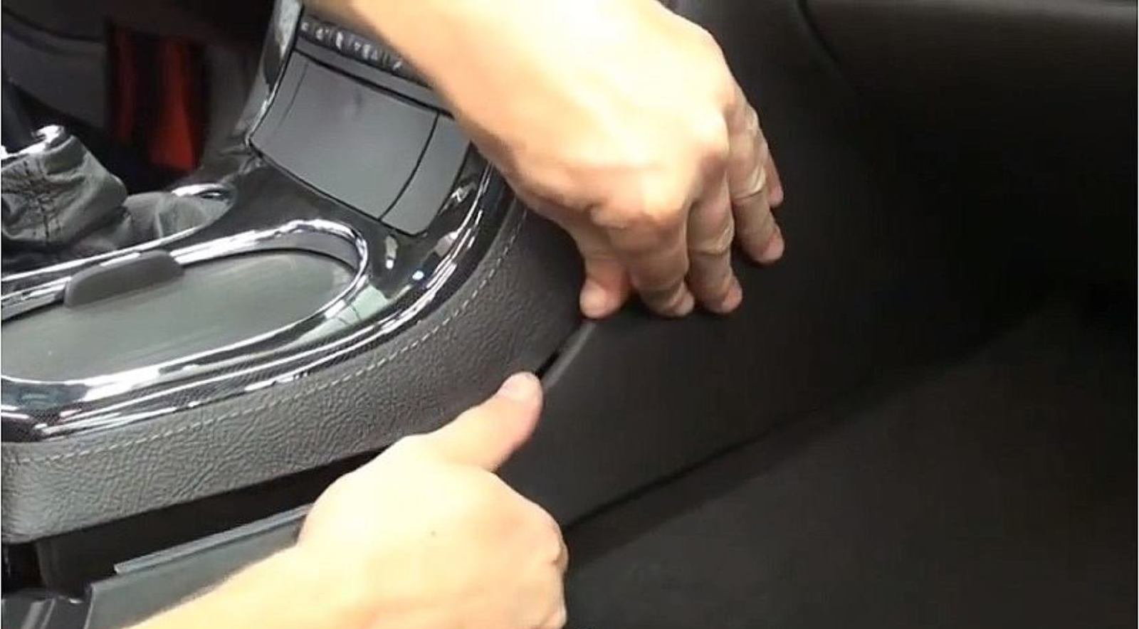
Step 6 – Remove the lower console trim piece on the passenger side
Remove the lower console trim piece on the passenger side. It is held in with two metal spring clips located on the storage box’s left side trim. Carefully pull down the rear of this trim piece, outward on its center, and away from the storage box to pop it out. A top groove running along the back of this trim piece fits under the center console lip to hold it in place.
Step 7 – Remove the console
Starting with the rear of the console, carefully tilt it up and then pull it back, un-clipping the hidden attachments along the way. Work your hands up behind the vertical console bezel to pull the unit about an inch away from its mount location. For a manual transmission, pull the shifter back, and pull the boot up over the shaft.
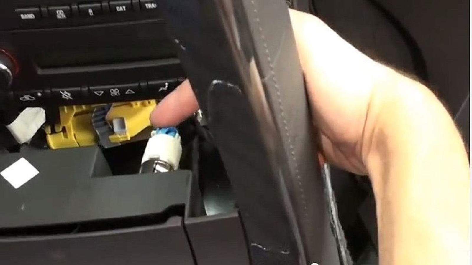
Step 8 – Un-clip the hazard light
Reach behind the bezel between the HVAC vents to un-clip the hazard light. The connection has a side tab that must be pushed in before the plug can be disconnected.
Step 9 – Un-clip any additional switches
On some models, additional switches are located to the left and right of the ashtray. If these are present, they are disconnected the same way as the hazard light.
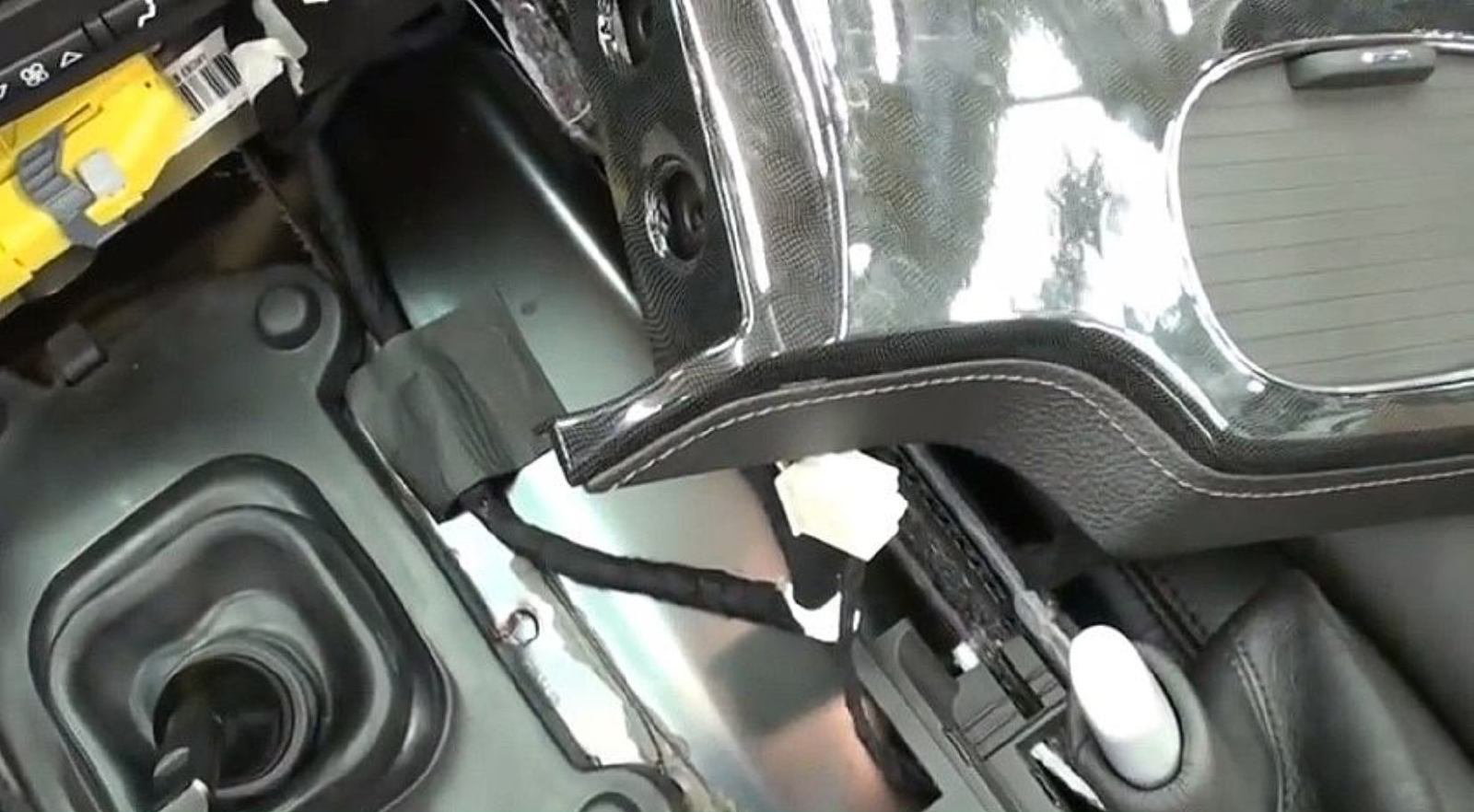
Step 10 – Reveal and un-clip the cigarette lighter connection
Pull the console back a bit more to reveal the cigarette lighter connection, located on the right side of the ashtray. Inserting a small screwdriver or wrench into the hole on its side and pushing in a small pin allows it to be disconnected.
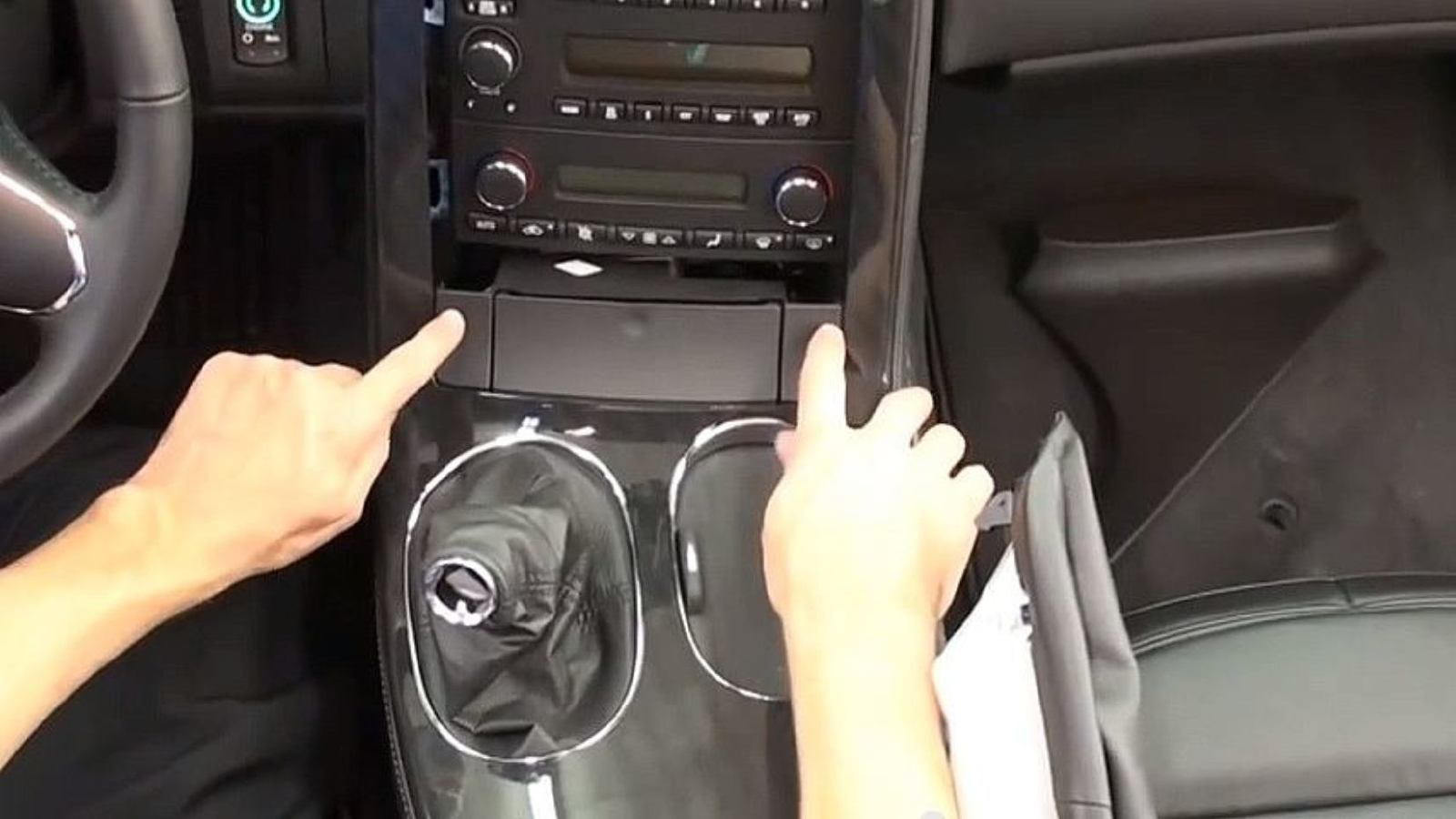
Step 11 – Drape the console over the passenger seat
Pull down the emergency brake boot over the lever and work the console up and over to the passenger side. Draped over the seat, the connections to the 12v plug and options such as Select Ride, located at the back console, can also be disconnected at this point. However, there is typically enough length to these tethered wires to effectively swing the entire console out of your way.
Step 12 – Remove the climate control unit for more room
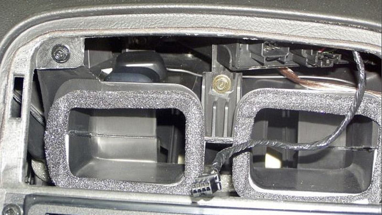
It can be a good idea at this point to also unplug and set aside the climate control unit, so you can have as much room in the radio cage as possible. Then, unscrew the four screws holding in the original double-DIN size radio, remove, and unplug it.
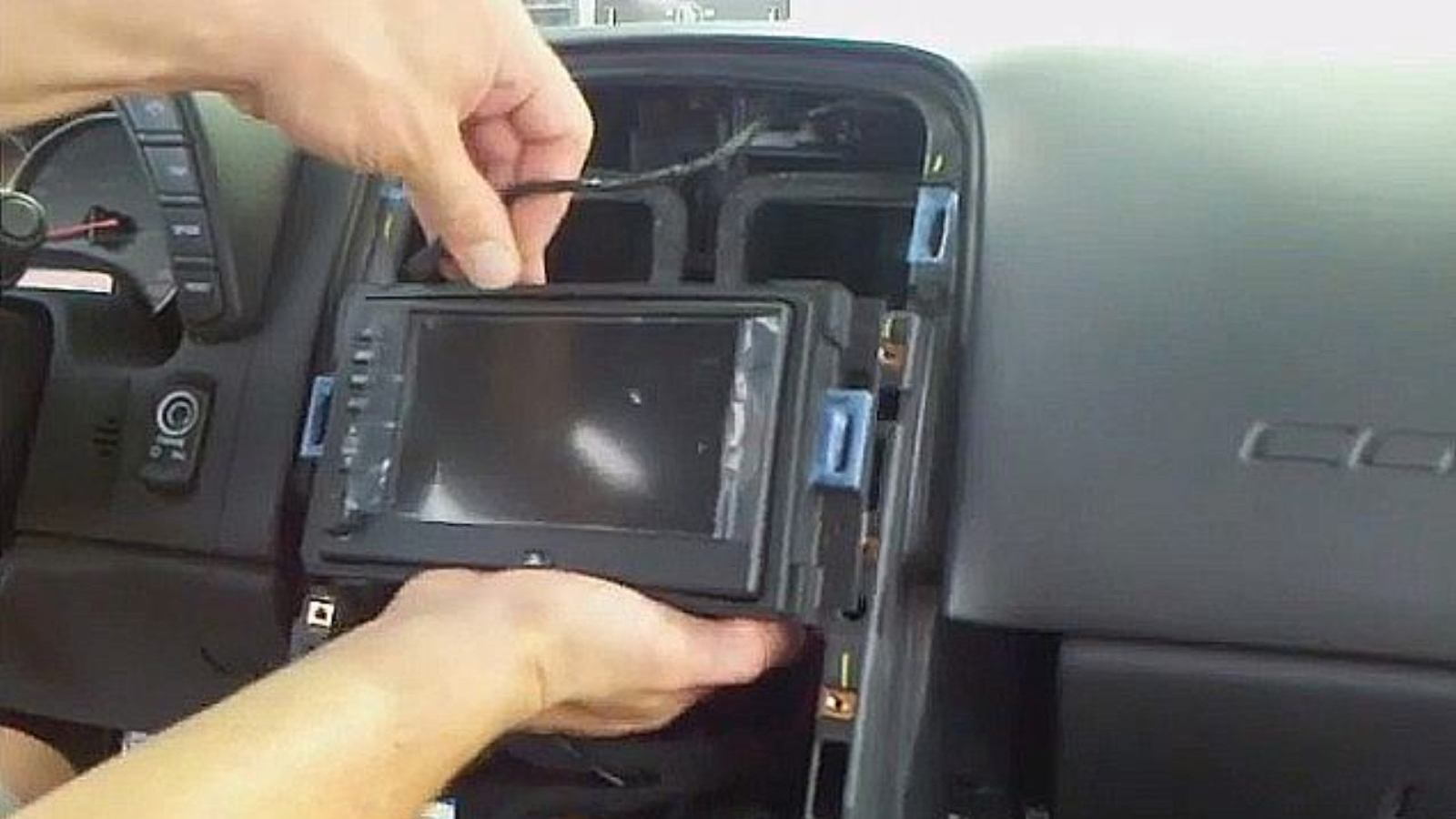
Step 13 – Plug in satellite antenna
Next, a satellite antenna (like Kenwood’s Navigation GPS Antenna designed to work with a number of their receivers, about $15) gets plugged into the navigation chassis. Although this antenna’s magnetic head was designed to stick to a car’s trunk lid or roof (which is why it has 18 or so feet of wire attached to it), it typically works best if stuck to a small steel plate (some antennas are available with such a plate included). The antenna and steel plate can then be mounted atop the left HVAC vent in the radio cage. This plate should be pushed forward to be under as much windshield glass as possible, and can be held in place with twin stick-type foam tape. The long, extra wire should be coiled up and secured with a zip tie, then placed within the radio cage area.
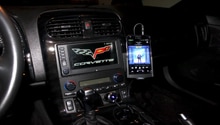
Before replacing the console, your new navigation receiver should be thoroughly tested.
Pro Tip
Don’t forget to first pull your vehicle out of the garage and under the open sky to test your GPS reception.
Featured Video: C6 Corvette Shifter & Console Removal
Installing the New Navigation
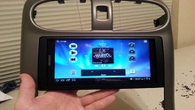
Connect the wires to the new navigation system; they should plug in the same way they were plugged into the old system. Then, screw the bezel in. If you buy an aftermarket navigation system that is sold specifically for Corvette, it won't come with a bezel, instead, it will fit right in. However, if you buy an aftermarket navigation system that isn't made for Corvette, you may need to purchase a dash kit that is designed to fit your Corvette. Most of the aftermarket navigation systems will come with a new bezel, in which case you may need to trim it using a file and sandpaper until it fits in your Corvette.
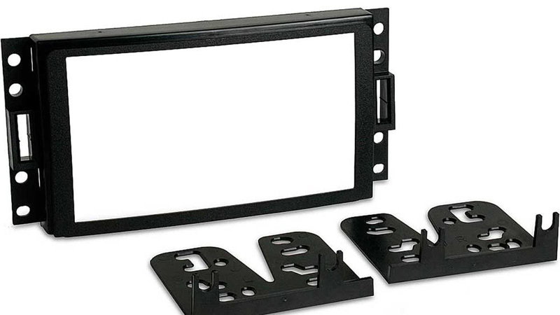
Figure 13. 2005-2008 dash kit 95-3304 from Metra. 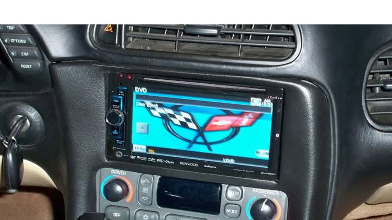
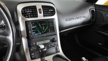
Figure 14. New navigation system installed.
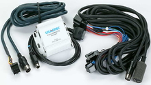
Installing a Wiring Interface Kit
If you purchased an aftermarket kit not specifically designed to fit your Corvette, you will need to splice and wire the now-revealed connections into your interface module wiring kit using the directions that came with it. The following list describes some choices, as well as their features.
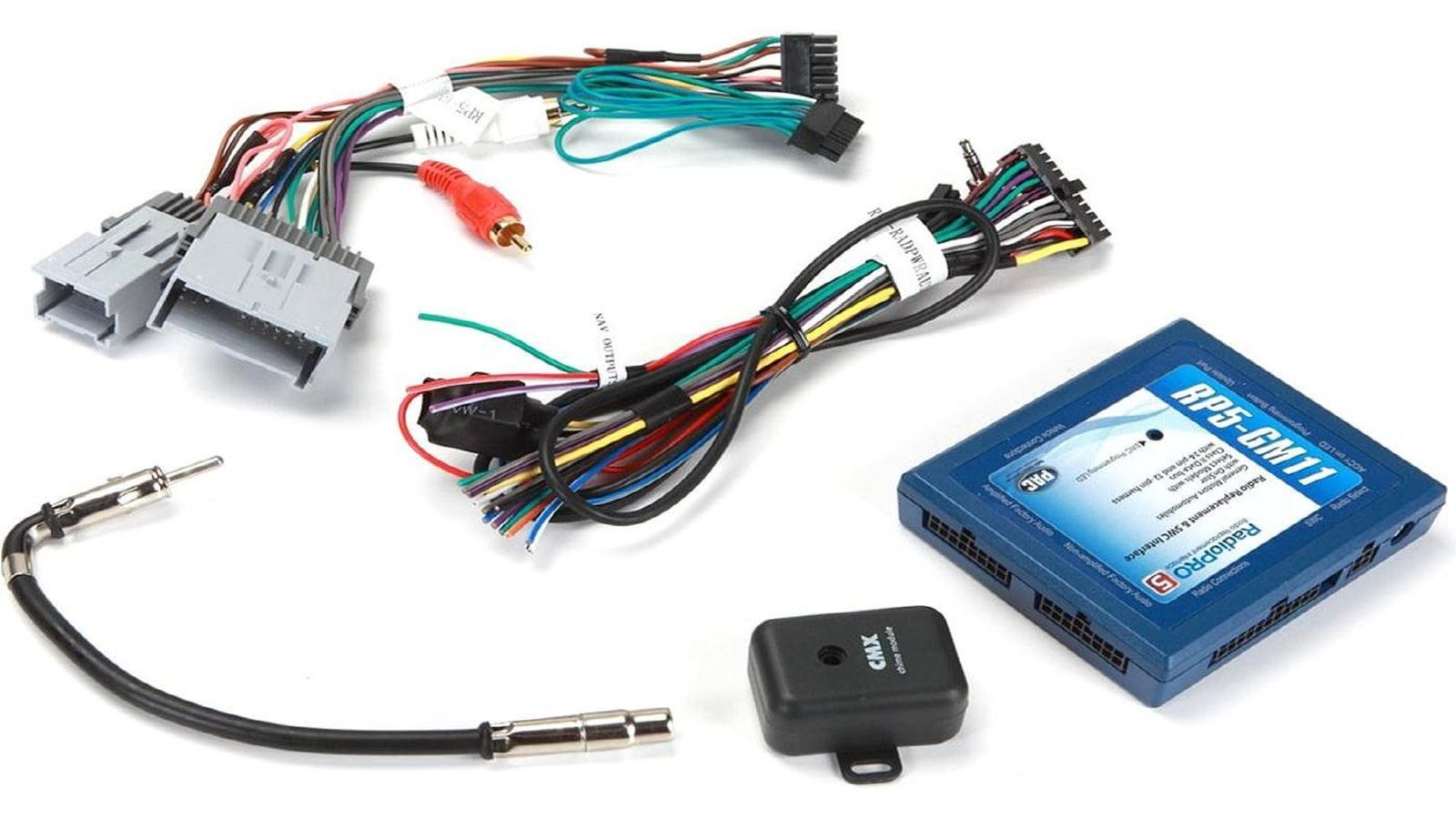
A popular solution is the RP5-GM11 wiring interface kit, from PAC (around $185). This unit retains OnStar (with volume adjustment), audible safety warnings and chimes (using a chime module), and claims compatibility with 2005 to 2013 Corvettes. It also:
- Works with GM vehicles with the CLASS II data systems
- Works with amplified and non-amplified systems (including Bose audio systems)
- Provides Vehicle Speed Sensor (VSS), parking brake, and reverse connections for a navigation receiver
- Retains factory Bluetooth if equipped (2009+ models)
- Retains factory steering wheel audio controls (SWC)
- Comes with an antenna adapter (GM to Motorola)
- Requires a single pole-double throw relay, such as the E-5000 from Metra (about $15) for turning on and off high-current devices
Another is the VT-GMOS-04 wiring interface from Metra (around $100). This unit also retains OnStar, audible safety warnings and chimes, as well as the Bose audio system. It claims compatibility with 2005 to 2010 Corvettes, and:
- Provides Vehicle Speed Sensor (VSS), parking brake, and reverse connections for a navigation receiver
- For steering wheel audio control (SWC) functionality, this unit requires another module, such as the ASWC-1 Steering Wheel Control Adapter from Axxess (around $80), which plugs into your navigation head unit via its 3.5mm SWC input or wired remote connection. Note that this unit doesn’t retain your vehicle’s factory Bluetooth functionality.
- Another steering wheel control adapter is the ADS-MSW Steering Wheel Control Adapter from iDatalink (about $80). Before installation you must flash the unit with firmware for your vehicle using a PC. This unit also plugs into your navigation head unit via its 3.5mm SWC input or wired remote connection.
- Requires an antenna adapter, such as the 40-GM10 from Metra (around $10)
- Also requires a single pole-double throw relay, such as the E-5000 from Metra (about $15) for turning on and off high-current devices

Related Discussions and Site
- Navigation Unit Installation Discussion - Corvetteforum.com
- Aftermarket Sound Systems and Navigation Receivers - Corvetteforum.com
- C6 Scan & Tune After Market Navigation - Corvetteforum.com
- Antenna Location - Corvetteforum.com
- Breakdown of Units That Can Be Installed and Their Differences - Corvetteforum.com
- Good Information About Upgrading the C6 Sound System - Crutchfield.com